Electro Tech is an online community (with over 170,000 members) who enjoy talking about and building electronic circuits, projects and gadgets. To participate you need to register. Registration is free. Click here to register now.
Welcome to our site! Electro Tech is an online community (with over 170,000 members) who enjoy talking about and building electronic circuits, projects and gadgets. To participate you need to register. Registration is free. Click here to register now.
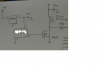
I have a problem with my amplifier circuit.when I measure voltage at the terminal of the dc blockin capacitor as i have given in the following picture it shows low close to zero and the frequency about 300 khz.what is the problem ?please help me someone.
I'm not sure that the IRF510 will switch at 2MHz. If it will though, you'll need a higher current gate drive circuit - the gate capacatance of a large MOSFET causes it to sink significant current at such high frequencies, and a standard TTL output isn't up to it. You'll probaly find you need a higher voltage too - 10v is more typical.
What's the purpose of this circuit?
'The purpose is to transfer power wirelessly.The out put of this circuit will be given to a LC circuit which will also resonate at 2Mhz.As you were saying can I give a signal from a signal generator which can give voltage 10v or above? Though according to the principle it should give the same 2 MHZ frequency at the output why it is not giving output at that frequency?I am getting about 300khz?please suggest a solution?
Make sure you drive the MOSFET hard enough. I don't have experience with the IRF510 but the IRF520 should work well at that frequency. Also try placing a 27 ohm resistor parallel with the inductor to reduce the chance of a 300khz tuned circuit at the output.
Make sure you drive the MOSFET hard enough. I don't have experience with the IRF510 but the IRF520 should work well at that frequency. Also try placing a 27 ohm resistor parallel with the inductor to reduce the chance of a 300khz tuned circuit at the output.
what will happen if i place a 27 ohm resistor parallel with inductor?i need 2 mhz at the output?and the theory also says that the output frequency should be 2mhz.
You're right that there should be no 300kHz there - the only thing I can think of is that there is a parasitic oscillation there somewhere. As BeerBelly suggests, there could be an unexpected tuned circuit disturbing the operation. Alternatively, maybe the voltage regulator is oscillating or the crystal module is being upset be such a high load?
This site uses cookies to help personalise content, tailor your experience and to keep you logged in if you register.
By continuing to use this site, you are consenting to our use of cookies.