Continue to Site

Welcome to our site!

Electro Tech is an online community (with over 170,000 members) who enjoy talking about and building electronic circuits, projects and gadgets. To participate you need to register. Registration is free. Click here to register now.

  • Welcome to our site! Electro Tech is an online community (with over 170,000 members) who enjoy talking about and building electronic circuits, projects and gadgets. To participate you need to register. Registration is free. Click here to register now.

time delay relay

Status
Not open for further replies.

manz

New Member
hi again...

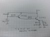
I`ve built a "power-on time delay relay" from a circuit that I got somewhere on the net (can`t remember where).It is to switch on something (could be anything,depends on the connection of the relay) after certain amount of time.

The problem :

1. At first the timer seems to work perfectly but after a few time using it, the timer just failed to work (but on,just not delayed)

The situation:

1. I know it could be easier if I paste the circuit here but I just dont have the schematic in the computer.It is very simple and i just draw it and didnt save the schematic.

2. I tested it by using the ac to dc adaptor (input: 240v/50Hz)rated output :12v dc /500mA/9W and it works perfectly ok even after many times using it.

3.Then I transfered the circuit to be used in the car powered by the car battery rated 12v dc / 65AH and after several time using it, the timer just fail to works.I knew the power supply is so much more different and the circuit failed due to this.(should be).

***For the info, the circuit uses 2 of 2N3904 and 1 of 2N3053, a capacitor and a resistor and a relay.( :idea: hope you can imagine how`s the circuit connection :idea: )

The question:

1. Is it because of the transistor (either 3904 or 3053) input voltage I used to supply it too high?

2. Or is it because of the current supply to high for the circuit?

3. can i use a voltage regulator something like 78L05 or 78L06 or anything (i didn`t know which is on the market other than 78L05,please suggest me) to reduce the feeding voltage to the circuit.because i`m using 6v/9v/12v relay with the circuit..

4.If there is any other way to make the circuit works with the car batt,please let me know.

Since I didn`t put the shematic I know maybe it is hard to help me out but maybe some of you just can do the magic :wink:

if it is realy hard without the shematic, i`ll try work it out to paste it here.

Realy appreciate your help, thanks.
 
What load were you switching in the car?
Is it just that the relay contacts are welded together from switching to high a load current?

JimB
 
manz wrote:
1. Is it because of the transistor (either 3904 or 3053) input voltage I used to supply it too high?
It can not only be the transitor but other components
There are many kind of surges and spikes over the power line of the car
(normal range of battery voltage is from 9V to 16V for normal operation and it goes upto 24V for around one minute during start and then there are other spikes and surges due to operation of various solenoids and motor loads in car) and which may have damaged any component because of exceeding the specifications of particular component

2. Or is it because of the current supply to high for the circuit?
The current rating of battery specifies how much it can supply, it will supply only as required by circuit, so this rating is no reason for your circuit not working

3. can i use a voltage regulator something like 78L05 or 78L06 or anything (i didn`t know which is on the market other than 78L05,please suggest me) to reduce the feeding voltage to the circuit.because i`m using 6v/9v/12v relay with the circuit..
Yes it is always recommended to use voltage regulators when using supply form car battery
and 7806, 7809 and 7812 are available in market
 
hi JimB...

JimB said:
What load were you switching in the car?
Is it just that the relay contacts are welded together from switching to high a load current?

JimB

1. Ok, I use the circuit to switch the head lamp of the car. The relay is just as a switch (bypass the normally operated that is by hand).

2. I combained 2 circuits for this purpose. Firstly is the "dark activated circuit" that is to measure the light intensity and this will switch on the timer circuit so that it will only switch on the head lamp after several second of continuous darkness as i pre-set it.

3.so i think where the relay is connected doesn`t matter (should be :wink: ) as it never will affect the timer circuit.The timer circuit just will selenoid the relay.

thanks..
 
Hi instruite..


It can not only be the transitor but other components
There are many kind of surges and spikes over the power line of the car
(normal range of battery voltage is from 9V to 16V for normal operation and it goes upto 24V for around one minute during start and then there are other spikes and surges due to operation of various solenoids and motor loads in car) and which may have damaged any component because of exceeding the specifications of particular component

1. Yes i`m aware about that. i`ve measure the voltage (engine on and off) the battery voltage varries just from 9V to 14V (for my car though)

2. I dont think that any other device that is faulty because as I posted earlier the circuit just using those transistors, capacitor, resistor and lastly a relay and diode that is in parallel with it.(it should be the transistor,I think :wink: )

3. I need to know the maximum voltage that can be supply to the transistor (2N3904 and 2N 3053) so that I`ll know which voltage regulator can be added to the circuit (if it is the voltage is the matter that cauused the faulty in the first place)

thanks guys...
 
HI manz:
1. Yes i`m aware about that. i`ve measure the voltage (engine on and off) the battery voltage varries just from 9V to 14V (for my car though)
If you measure it with multimeter you never will be able to measure spike voltage which is of 100Vs but of very short duration of nanoseconds and microseconds
Normally components can handle such voltages for such short durations (but it might not be true for all components)

2. I dont think that any other device that is faulty because as I posted earlier the circuit just using those transistors, capacitor, resistor and lastly a relay and diode that is in parallel with it.(it should be the transistor,I think )
In our designs we take care special care in resistor wattage selection because those are the components which can blow up easier during surge due to high power dissipation through them during surges

3. I need to know the maximum voltage that can be supply to the transistor (2N3904 and 2N3053) so that I`ll know which voltage regulator can be added to the circuit (if it is the voltage is the matter that cauused the faulty in the first place)
2N3904 - **broken link removed**
2N3053 - **broken link removed**
 
Possible cause: overdissipation during timing period. Without sematic i only think the circuit not a schmitt-trigger, so the transistor work in linear mode, not in switch-mode.
 
Depending on your circuit connection, the capacitor that you have is driving the base of transitor, you have to be sure that you will not oversaturate emitter-base junction, make sure you have a current limiting resistor. It would help if you show your circuit. The schmitt-trigger is not required, since the relay only pulls in at a specific treshold and then stays on.
 
electronic spark said:
Depending on your circuit connection, the capacitor that you have is driving the base of transitor, you have to be sure that you will not oversaturate emitter-base junction, make sure you have a current limiting resistor. It would help if you show your circuit. The schmitt-trigger is not required, since the relay only pulls in at a specific treshold and then stays on.

hi ES,
Seen the date of the last thread, 2005....:)
 
I was looking for a circuit myself for a 5 min on delay timer for the car to use with relay that turns on O2 signal conditioning circuit for fuel economy. Since I didn't find one I designed my own, using 2 transistors 2n222, few resistors, 100u electrolytic cap and relay. I'll post the circuit later.
(I noticed the post date after I replied :):eek:
 
Here is the circuit.

hmmm can't seem to insert or attach a picture of diagram? maybe..
 

Attachments

  • 5min timer.jpg
    5min timer.jpg
    223.2 KB · Views: 508
Status
Not open for further replies.

Latest threads

New Articles From Microcontroller Tips

Back
Top