Hi,
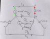
Let me explain using your drawing.
The load for phase A for example is connected across the two RED dots. This is the same as the two GREEN dots for this circuit but later if we remove the neutral it wont be the green dots just the red dots.
So first we do a calculation with no extra components.
Next, if we are to connect 100 ohm resistors, we first connect 100 ohm across the two red dots, but do the same on all three phases if doing all three phases, then do a calculation and that calculation leads possibly a different amplitude and phase angle.
Next, we connect another 100 ohm resistor in parallel with the first one, which gives us a total of 50 ohms (two 100 in parallel) across the red dots, and the same on all three phases if we are doing all three phases the same.
Next, we connect still yet another 100 ohm resistor in parallel to that, so that puts a 50 ohm in parallel with a 100 ohm.
Next, and finally, we connect a fourth 100 ohm resistor across that, so we end up with phase A (and other phases) with only 25 ohms across it as well as whatever was originally there (like the inductor from the original problem).
The only change in the above is if we only do one phase, like phase A, then we only connect resistors across phase A and no other phases. If doing two phases, then we only connect resistors across those two phases, and if doing all three phases we connect them across all three phases. So doing all three phases we would do:
1. 100 ohm across phase A, another 100 ohm across phase B, another across C. That's three different resistors.
2. Next, another 100 ohm across each phase, which would be three more resistors unless we combine them in parallel and only use one 50 ohm resistor for each phase.
3. Next, another resistor on each phase.
4. Finally, one more resistor across each phase so each phase now has a total of 25 ohms across it (four 100 ohm resistors in parallel is 25 ohms).
If we use capacitors we do it with caps instead of resistors.
After each change, we do another calculation and record the resulting amplitude and phase angle.
The whole idea is to generate more examples, so by stepping the loads to each phase we can get a variety of examples (and tests) to work with. Doing them by hand should lead to the same results as the posted values.
I have it set up now where i can add any element across any phase and get a result in as long as it takes to enter the values. If the values are stepped, then i can show several results after entering the base values and the step value.
I did this so we could look at more examples without having to calculate every single one by hand which takes forever
")
I could probably rig it up to do the circuit with no neutral too, given another 15 minutes or so.