PG1995
Active Member
Thank you, MrAl.
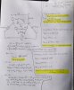
Please have a look here. The voltage across terminals "A" and "B" is same as that between "A" and 'fake neutral' (red dot) or as that between "B" and 'fake neutral'. In my humble opinion, I don't think there would be any difference between line-to-line or line-to-'fake neutral' voltage. Do I have this correct? Please let me know. Thanks.
Q:
Suppose we have a 240V single phase generator. We will assume that the generator is not grounded; there are only live and neutral wires. (Technically, I believe that both wires should be considered live). Anyway, suppose that someone accidentally touches live wire, will he get electric shock?
If you have time, please also help me with Q2 and Q3 from my previous post. Thank you.
Regards
PG
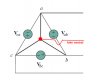
Most of the delta's i have seen only have an earth ground, which means it does not connect to any winding. It looks like it is totally separate from the windings.
The delta can be loaded line to line or line to 'fake' neutral. The fake neutral is just the point where the three loads connect together like those three capacitor looking things in your drawing. The voltage then is obviously lower because it would be line to 'neutral' rather than line to line.
Please have a look here. The voltage across terminals "A" and "B" is same as that between "A" and 'fake neutral' (red dot) or as that between "B" and 'fake neutral'. In my humble opinion, I don't think there would be any difference between line-to-line or line-to-'fake neutral' voltage. Do I have this correct? Please let me know. Thanks.
Q:
Suppose we have a 240V single phase generator. We will assume that the generator is not grounded; there are only live and neutral wires. (Technically, I believe that both wires should be considered live). Anyway, suppose that someone accidentally touches live wire, will he get electric shock?
If you have time, please also help me with Q2 and Q3 from my previous post. Thank you.
Regards
PG
")
")