I found this here, and began to look at it thoroughly.
**broken link removed**
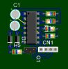
It seems to me that this circuit does not need to use a IC 4001. You can just make two transistor OR gates and get the same results. I would like to make this much smaller, and could use some help on it. I've been out of the electronics field for 9 years or so, so I am very rusty")
This unit is used on an electric drum set. The drum brain sends ~3.3v to the single foot pedal, and pressing the foot pedal makes a switch to complete that circuit.
The point of creating this, is to be able to use two foot pedals on the same circuit, but the trick is to be able to use either pedal, reguardless if the other pedal is up or down.
To make this circuit currently, I can do it on about 1.5x1.5" 2 layer PCB, but if I can shrink it, I would like to. I was thinking that the chip itself can be eliminated, but maybe my own logic is too rusty to see where I may be wrong.
Thanks,
Adam
**broken link removed**
It seems to me that this circuit does not need to use a IC 4001. You can just make two transistor OR gates and get the same results. I would like to make this much smaller, and could use some help on it. I've been out of the electronics field for 9 years or so, so I am very rusty
This unit is used on an electric drum set. The drum brain sends ~3.3v to the single foot pedal, and pressing the foot pedal makes a switch to complete that circuit.
The point of creating this, is to be able to use two foot pedals on the same circuit, but the trick is to be able to use either pedal, reguardless if the other pedal is up or down.
To make this circuit currently, I can do it on about 1.5x1.5" 2 layer PCB, but if I can shrink it, I would like to. I was thinking that the chip itself can be eliminated, but maybe my own logic is too rusty to see where I may be wrong.
Thanks,
Adam
Last edited:
")

