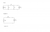
Ok, I found some practice problems online and I need help with the one in the schematic. I don't see how they get the answer. So the main schematic is shown above and I simplified it below. What I did was: 2.25Ω x 0.8A to find the voltage drop across the 2.25Ω resistor. I get 1.8 and then apparently I add that to the 1.2V source (Don't know why) and I get 3V. Can someone please explain why I do that?
1st step : open the terminal under test (Is2)
find Rth
for independent current source - open circuit
for independent voltage source - short circuit
so in this case both current sources Is1 and Is2 are open
by looking from terminal Is2,
6ohm and 3ohm are seen connected in series with equivalent resistance
of 9ohm. The 9ohm is seen parallel with 3ohm resistor(which is also
parallel to the terminal under test
so Rth = (9*3)/(9+3) =27/12 = 2.25ohm
or if its confusing try this method with Is1 and Is2 still open
place a test voltage, Vth, on the terminal under test and Isc going into the
node between both the 3ohm resistor
now you have a mesh circuit and use KVL
draw mesh curent clockwise I1 on mesh 1 and I2 on mesh2
where Isc= -I2
you be able to arrive to these equation
12I1 - 3I2 = 0
-3I1 + 3I2 = -Vth
solve for I2 where I2 = -(12Vth)/27 = - Isc
therefore Vth/Isc = 27/12 =Rth
Rth = 2.25 ohm
to find Vth
Vth is the voltage drop on the 3ohm resistor parallel to the terminal under test
place back Is1 but Is2 remains open and place V on the 6 ohm resistor
use KCL
you should be abale to derive this equation
(V/6) + (V/6) + 0.8 = 0
solve and V = -2.4V
so voltage drop on 3ohm resistor = [ 3/(3+3) ] * (-2.4) = -1.2V