Continue to Site

Welcome to our site!

Electro Tech is an online community (with over 170,000 members) who enjoy talking about and building electronic circuits, projects and gadgets. To participate you need to register. Registration is free. Click here to register now.

  • Welcome to our site! Electro Tech is an online community (with over 170,000 members) who enjoy talking about and building electronic circuits, projects and gadgets. To participate you need to register. Registration is free. Click here to register now.

Thermocouple Temperature Controller

Status
Not open for further replies.

curoi

New Member
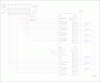
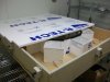
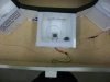
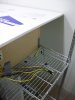
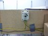
I've been tasked with building a thermocouple setup to control the temperature of growth chambers for a entomology project. I have almost no experience with electronics. For the project, we have 8 or so insulated chambers in which metal plates will heat up petri dishes that the insects have colonized. There is an optimal range in which each chamber will be maintained. These heating plates are already each connected to a set of thermocouples. So I'm trying to figure out how to connect the thermocouples to the controller (Omega CN1507 Multi-Zone Ramp and Soak Controller) and to the relay device (Omega Universal Relay Module). Anyone have any ideas?
 
If you control using the thermocouples embedded in the heater plates you will be controlling the plate temperature and dish bottom temperature more than the actual zone, the zone being the chamber environment. If that works for you then fine.

I assume that you have the controller manual.

How do the thermocouple leads exit the plates? Do you just have thermocouple leads? What type thermocouples are used as in Type? There are many types as to their ranges such as Type J, Type K, Type Whatever? You will need to know the TC type to set up the controller. Nice controller by the way.

So let us know the TC type and what you want to control as in dish bottom or the zone (chamber).

Ron
 
The thermocouple leads exit the square plates at the back corners facing away from the front of the chamber and the wires exit the chamber at the back. All the chambers are made of styrofoam insulation and are arranged in a circular pattern facing one another encased in a larger wooden case. The thermocouples are Type T thermocouples.

I had not originally set up the beginning part of these growth chambers. I think that the intent was to heat the petri dish directly rather than the chamber considering it is made out of styrofoam. In effect the dish will heat the chamber anyway but the actual controls will be govern the metal plate's temperature. I can post a picture of the entire setup tomorrow if that would help.
 
A picture would be nice. OK, type T is no problem and for low temps is a good choice. We will need to interface the controller outputs to the heaters. This is where we need to know the heater plate(s) voltage and wattage or current. That is important. Connecting the thermocouples to the controller will be no problem as long as the leads are long enough. Get the heater plate data and tomorrow I'll give you some ideas.

Ron
 
The hot plates are actually just two metal plates that appear to be glued together with caulking or something. The thermocouple is wired straight in between the two plates. And actually, the thermocouple wire is connected to a dimmer and then the dimmer will be connected to the control box. So I'm not actually sure what the voltage or the current is for the plates. I could not find any documentation for it. The dimmers are 12V 0.8A. Other than that I don't have any info on the the heating plates. I'll post a picture sometime today.
 
OK, then we can assume these low temperature plates obviously draw less than an amp at 12 volts. The dimmers were the original temperature control method. Looking forward to seeing a few pictures.

Ron
 
Pictures uploaded!

Whole Setup:

Chamber View:

Thermocouple lead ends:

Dimmer:

Controller:

Relay:
 

Attachments

  • 100_0243.JPG
    100_0243.JPG
    1.1 MB · Views: 244
  • 100_0247.JPG
    100_0247.JPG
    1 MB · Views: 239
  • 100_0248.JPG
    100_0248.JPG
    1 MB · Views: 217
  • 100_0249.JPG
    100_0249.JPG
    1.6 MB · Views: 237
  • 100_0250.JPG
    100_0250.JPG
    978 KB · Views: 244
  • 100_0253.JPG
    100_0253.JPG
    1 MB · Views: 234
OK, great images. You caught me in Conn on the road. The TC wires are obviously the very fine wires. What I can't see is they look to be red and white which would be common for a J type but you should have T type and that would be more commonly Red and Blue. What colors are they and you are sure about type T correct? Anyway, generally the with thermocouple leads the Red is generally Negative (-).

Originally the system was intended to be used with the 12 volt dimmers. Looks like each dimmer supplied two heater elements. Now I saw the Omega relay system, what is the part number?

I am at a disadvantage traveling as the laptop lacks my drawing software but we can get started. I try to get to the forums catch and catch can.

Ron
 
Hey Ron,

It's been awhile. I double checked the thermocouples and they are red and blue. Also, the packaging number indicated that they were type T.

I think you're right about the dimmer supplying two heater elements. The relay system is a Relay-URM-800. I should be more responsive in the coming weeks.

Thanks
 
Thought you fell off the planet. :)

No problem as my highest latest and greatest priority at work today will be around #10 in a week or so. I know that deal.

That makes sense with the red and blue (Red is Neg and Blue is Pos from the TC) and I now understand the relay controller. Obviously the TC leads will go to the temperature controller's TC inputs observing polarity. Give me several days and we will work out the rest.

Ron
 
I'll but in temporarily.

1) The dimmer is located here: https://cgi.ebay.com/12v-12-v-LED-s...US-seller-/360276691806?pt=LH_DefaultDomain_0 Looks like a PWM controller for 12V DC

That out of the way. What are you using for a 12 V power source? Do you know the power requirements for the heaters?

I would reccomend playing with a single channel before wiring all eight.

This very well could be an undauting project for someone unfamiliar with temperature control and electronics in general.

The controller may or may not be suitable and it will be a wait and see prospect. I don;t have a feeling for on/off time, response time of the dimmer, the thermal mass or the temperature range being controlled.

It's definately a way different output model than I'm used to. I'll use the word inexpensive, but not guaranteed method of control.

You need a 12 V power supply. Current rating depends on what you need. 8 channels at 1A may be more expensive than it need be. That would be an 80 W power supply. Think of the heat output by two 40 W light bulbs. The dimmer is about the amount of heat from a 7W night light.

The "light" will effectively blink at some rate the dimmer in effect makes it a variable wattage light bulb.

All I'm trying to do is to get you to "visualize" the system.

Based on the info I've seen, your missing one key component. A 12 V power supply. Regulated would be preferred.

You need to have an idea of what the current and voltage requirements are.
 
I'll have a basic drawing for you by tomorrow afternoon (Sunday) build around what you have and how I would think about doing it.

Ron
 
Attached is a basic circuit drawing (cartoon) of how I believe you want to set things up. Sorry about the size. As to the heater power, I drew it as single supply. I am not sure how you were supplying the dimmers? If you have a supply that was supplying the dimmers, then we can use it. I noticed the dimmers were DC in and out.

As questions arise, let us know.

Ron
 

Attachments

  • Omega Controller CKT..gif
    Omega Controller CKT..gif
    157 KB · Views: 237
The dimmers are DC in, PWM out.

Then there should be a DC power supply lurking out there somewhere.

These chambers don't really generate much heat all all, I am guessing. I am guessing they are pretty low power.

Before actual temperature control was introduced into the scheme the idea was likely to just mess with the PWM till the temperatures were about right. Sort of a set it, forget it type affair. Again, pure speculation on my part. How well the controller maintains and controls will be a function of the mode it controls with. I figure get things wired (I think I drew it up correctly) and work from there. Yet to be known is if a DC supply exist or yet needs to be bought? Beats me.

Ron
 
Your thinking on the same lines I am. It may or may not work. When something has little thermal mass all you end up with is excursions with on/off control or even duty cycle based control based. In any event, it's not proportional control of the power (voltage) to the heater.

It may run just fine without temperature control - just fixed voltage to the heaters. The controller could just monitor temperature.

BUT, if the mass is small and the burst amount of heat is small, it could work. Soft-start circuits, if any, in the dimmer COULD cause issues.

I figure it this way KISS. Looking back at the posted images there is one image that shows what looks to be a tiny (as in real tiny) heating pad with a petri dish sitting on it. There is also what looks to be very, very fine thermocouple lead extending from the center. That would run with the poster's description. I agree a simple approach would just be to PWM the pad and look for the "sweet spot" while monitoring the temperature.

However, they invested close to $800 in a 7 zone controller plus about $200 in the relay module. My guess is they want to control the pad temperatures? While depending on project $1,000 is not a tremendous amount of capital they have something in mind. The controller offers PID or simple on/off control. How well would PID control work for such low temperatures? Beats me and yet to be seen but I am guessing this is low temperature using a heating pad slightly larger than a postage stamp and getting temperature from inside the pad. It should play out interesting. :)

Ron
 
Do you have a heat sink attached to the bottom of those peltiers with a fan blowing across it? I didn't see a picture of the bottom, just wanted to make sure there was one.
 
Still need help.

So here is a description of the entire system just to help clarify. In the images of the whole system, the very, very fine thermocouple wires extend out of the center of the heating pad. There are also a set of black/red and black/yellow wires that run from the edges of the plates out of the box and into the dimmers (to be honest, I'm not sure what the dimmers are for). From my understanding, the thermocouple is not what is controlling the temperatures, but rather what is measuring it. Is that correct?
That would leave me to believe that the larger wires connected to the dimmer would control the power being supplied to the plates.

Also, if someone could explain what the function of the controller and the relay are in general that would be helpful. I literally do not know much of anything about electronics so if you could spell it out in laymen's terms as best as possible that would be helpful. Abbreviations and acronyms are hard for me to understand aside from AC and DC. We actually do have a DC power converter that plugs directly into the wall socket which makes me wonder if we even need the relay module at all. To me it sounds like the relay is just to drop the voltage from anywhere up to 250 volts back down to twelve. Is there a way I can just plug the DC power supply directly into the controller without the need for the relay?

The DC power converter wall plug has two wires, one brown and one white, but I'm not sure which wire is positive and which is negative.

If I do still need the relay module, then I can still use the diagram showing the thermocouple leads going into the controller. That part makes sense to me. What kind of wire runs from the open collector outputs to the relay though? I don't think I have those wires.

The temperature range that we are trying to achieve is anywhere from 0 to 40 degrees celsius. Are these temperatures too low for the PID controller.
 
Status
Not open for further replies.

Latest threads

Back
Top