Continue to Site

Welcome to our site!

Electro Tech is an online community (with over 170,000 members) who enjoy talking about and building electronic circuits, projects and gadgets. To participate you need to register. Registration is free. Click here to register now.

  • Welcome to our site! Electro Tech is an online community (with over 170,000 members) who enjoy talking about and building electronic circuits, projects and gadgets. To participate you need to register. Registration is free. Click here to register now.

Thermocouple conditioning & fluctuations

Status
Not open for further replies.

ustink007

New Member
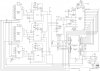
I am using National Instrument hardware (pci-6034e & CB-68LP) and labview 5.1 software for recording of temperature. After setup with these equipment i notice that the temperature wasn't too precise. In still water at constant temperature i get a range of 1.5 deg Celsius. Example: in water, ~25 deg Celsius (according the average of thermocouple readings), i get a thermocouple reading, through labview, of a minimum of ~24.5 and maximum of ~26.5.

I've tried a AD595 for the thermocouple and recorded the output voltage. I get the same result.

How would lessen these fluctuations?
 
Have you done any analysis on the fluctuations to determine if they're noise from the system or a coupled signal? If it's noise simply averaging them out over time will eliminate it, thermocouples generally don't have a fast response time anyways so you're not losing anything by averaging. The numbers you listed show your average right around the median of the high and low reading, assuming you used more than two readings it looks like noise to me, perhaps more decoupling on the AD595, more general decoupling and low pass filters on the thermocouple leads, maybe ferrite bead or three, one on each lead and one in common.
 
Last edited:
Thermocouple sensors are good choice for higher temperature applications. Thermocouple output signal is too small ! You need see the some Thermocouple Reference Tables , for better understanding how small voltage changes get a range of 1.5 deg Celsius.
thermocouples and thermocouple probes
In Your situation I think, temperature fluctuations are very normaly.
 
Janis, it's not the absolute accuracy he's having problem with it's signal variation outside of what should be expected from the material it's placed in. According to the PDF of his IC the temperature stability of the device is pretty course, however he shouldn't be getting that much variation from the thermocouple itself. Could be a coupled signal from another part of the circuit or thermal fluctuations in the IC itself. The IC he chose is pretty temperature stable so I'm guessing it's coupled noise. Unless the IC is near something that varies temperature widely.
 
How would lessen these fluctuations?

You might try gentle agitation of the water.
The idea is to mix the different thermal zones or gradients within the container, resulting in a more uniform or homogeneous temperature distribution.

... Not sure what to suggest as far as a mixing device...
maybe some sort of propeller attached to an electric motor.
Too much speed might add heat to the container, though.
 
user 88. You think his thermocouple is precise enough to measure those thermal zones? Worth a shot I guess. What 'we' would consider a substance of a same temperature is VERY course compared to a thermocouple.
 
I'm trying to figure out if it's noise problem. With help of a National Instrument i attempted to do a spectrum analysis, and it was determined it was not noise. But i'm not completely convinced.

I've used the same setup on multiple computers at multiple locations. I'ved used small 2-3 inch thermocouple to a 12" thermocouple with 5' extension cable.

As for thermal fluctuation. Unless it's coming from the computer PCI card. I'm clueless.

I've also tried multiple medians. Water, air, and even embedded in a composite laminate.

Well, what i'm trying to figure out is if i can make my temperature reading as close to reading i would get from expensive signal conditioning, although i'm sure i'll get what i pay for.
 
If you get the noise still after all that, try bypassing the hell out of your existing circuit using resistors in series with capacitors as low pass filters. Use ferrite beads to reduce RF pickup all that.
 
One simple performance test of your hardware would be to begin a temperature measurement, note the reading, and then take a heat source, such as a heat gun, or maybe a hair dryer, and apply a moderate heat flux to the various measuring components of the circuit .... noting any changes as a result of the applied heat.
This might give you an indication of any components or circuits that are particularly sensitive to ambient temperature variation.
 
ad595 and k type Tc oscillation problems

Hi ,
I am making a data acqusation system with 20 K type thermocouples.my connection are are thmermocouple>maleconnector>female cooncteyor>sheldedwire of 15-20 cm >wire end soldered on pcb>muxdg407>ad595cq>muxDG406>adc ad574>89C52>pc .
I have got the prolem of fluctions/oscillations.when only one thermocouple is connected i get small data varation of 2-3 oC(continuous oscillations :'() but if 2 thermocouples are connected the tmep get out of control to 200 to 500 .even at room temp.also when i put my thermocouple in hot water.
I have earth the the body of thermocouple and grounded pin-1 of ad595.if i donot ground it my output goes to zero even if thermocouple body is earthed.
plz if any one can suggest a solution. or tell me what and where the probem is.Thanks :'( :-/. I spent a lot of time on this but no use i really need help thanks.....
i have tried low pass filtering but it made the system even more worse....
 
Hi, Janis
thanks 4 ur reply. My sechmeatic drawing is attached u can chk it. The microcontroller send adress to select mux channels one by one and then send the data value of all TC's to pc serially.
If i directely connect a TC to ad595 the noise problem is solved by connecting 8 TC to one ad595 through a mux is creating problem . I have used shelded thermocouple wire and green colour K type connectors. even then the problem is not solved. if u have any suggestions.Thanks
 

Attachments

  • Sechamatic1.JPG
    Sechamatic1.JPG
    187.9 KB · Views: 1,159
A couple of things,

The first is that very accurate temperature control is not the domain of thermocouples. On your Type K you can typically expect a hysterisis of +-1,5% on a Class 1 device and +-2,5% on a Class 2 device. You are currently getting about a 6% swing about a Class 2 specification.

Check what class thermocouple you have, if a Class 2 then this is as good as it gets. If a Class 1 then you are drifting too much. Check all connections and check that you have accounted for Cold Junction Compensation (this is to compensate for anomalies between the thermocouple joints, google it). Also thermocouples can have a high resistance so what often happens on installations is a compensation cable is used which is thicker and lowers the resitance. Typically your thermoucouple will be a up to 300mm long depending on the application and then compensation cable is used to connect to the controller / circuit.

Hope that helps
Andrew
 
Hi, ayeshasaftain.
Thanks, for reply.
I read some additional info. May be you already reading it, too. Maybe some researching experiments will be helpful for you ?
Some moments about multiplexed thermocouples Figure 11.from this AN about :
- all interconnects,
- enable input connection to + 5 volts, you are switching 3 enable inputs, 3 groups with sensors
- unused multiplexer inputs

And how with average temperature measuring Figure 10. from this AN ?
Regards, Janis
 

Attachments

  • AD595_AN369.pdf
    108.7 KB · Views: 570
Hi, thanks a lot 4 ur replies.
Andrew the IC ad595 I am using already includes cold junction compensation. and I am using both class1 and class2 device. and connected the thermocouple via shielded cable to the pc. don't the shelded cable of TC work as compensatrion cable.
Thanks Janis I have read the application notes but I donot know what type of isothermal block they are using .I have searched a lot on net but didn't find any such kind of block. if u have any idea?.
I can't afford oscilation of more than +-1 degree. when only one TC is connected situation is fine but connecting two or more make situation worse.
Andrew do i have to earth both class1 and class2 devices or there is some rule.
Thanks for ur time.
 
Hi.
Some links for info :
Capgo - Thermocouple Theory
class 1 and class 2 devices means only tolerance of sensors, I think.

**broken link removed**
find some more info about isothermal block
You have 3 mux - 3 groups of sensors.
1. connecting sensors only to one mux
2. connecting sensors only one to every mux
but as you read from AN , unconnected inputs you need grounded .
As web browsers I like more used Yahoo or Google.
Regards, Janis
 
Status
Not open for further replies.

Latest threads

New Articles From Microcontroller Tips

Back
Top