Continue to Site

Welcome to our site!

Electro Tech is an online community (with over 170,000 members) who enjoy talking about and building electronic circuits, projects and gadgets. To participate you need to register. Registration is free. Click here to register now.

  • Welcome to our site! Electro Tech is an online community (with over 170,000 members) who enjoy talking about and building electronic circuits, projects and gadgets. To participate you need to register. Registration is free. Click here to register now.

Tesla coil progress

Status
Not open for further replies.
Measure the diameter of the circle by using a set square and strait edge to draw two parallel lines, one from each side of the circle. Measure the distance between them. Divide by 2 and set your compasses to that value. If you want a number other than 6 you will have to do a bit of trigonometry. (Which when you were taught it in school you possibly thought it was a wast of time.)

Les.
Are you talking about something like this?
Yea, I've never been that great at math.
 

Attachments

  • C3DDB6D8-3ABA-42AF-A60B-CD9C5405B416.jpeg
    C3DDB6D8-3ABA-42AF-A60B-CD9C5405B416.jpeg
    1.5 MB · Views: 181
Last edited:
Yes that is what I meant to measure the diameter of the circle. Your 2" measurement is wrong. it should be 1,5" (3" x sine 30 deg which is 3" x 0.5 = 1.5") The horizontal distance of that point from the vertical center line of the circle will be 3" x cosine 30 Deg. which is 3" x 0.866 = 2.6"

Les.
 
Yes that is what I meant to measure the diameter of the circle. Your 2" measurement is wrong. it should be 1,5" (3" x sine 30 deg which is 3" x 0.5 = 1.5") The horizontal distance of that point from the vertical center line of the circle will be 3" x cosine 30 Deg. which is 3" x 0.866 = 2.6"

Les.
Thank you Les.
 
That might work if the center was even with the board, but it isn’t, so once the compass is at the 180 mark it is about an inch or so too far just by looking at it. If that isn’t the problem the radius is three inches when measured with the compass, but when marking from point to point around the circle it will always be too much because it lost some of its Circumference and it would now be a hexagon and not a circle.

Jim's idea does work. But for your project with the raised center, you have to modify it. Draw your circle, measure the resulting diameter of the circle, divide that by 2, that is your new radius. Then set you compass to the new radius, and pick a spot you want to start at. Put the point of the compass at that point and mark the circle with the compass(pencil end) and keep moving the point of the compass to the mark, once you do this clear around the circle you will have 6 equal points.
 
Ok now another question, how can I remove the metal casing for the fuse holder without damaging it? There doesn’t appear to be screws just the two small bolt-like things on the bottom. Disclaimer I am using the fuse holder to tap the primary.
 

Attachments

  • 573486D4-43AB-434A-A8D4-F27C9BD11FD7.jpeg
    573486D4-43AB-434A-A8D4-F27C9BD11FD7.jpeg
    4 MB · Views: 181
  • 9DC7550F-D3EA-4670-BCC0-146BEB4A30B3.jpeg
    9DC7550F-D3EA-4670-BCC0-146BEB4A30B3.jpeg
    2.6 MB · Views: 179
  • 211A6000-BF96-4C31-87D9-ACBFF0488190.jpeg
    211A6000-BF96-4C31-87D9-ACBFF0488190.jpeg
    2.8 MB · Views: 176
  • 721AF7C0-BB47-47D6-8946-3888EF4F787A.jpeg
    721AF7C0-BB47-47D6-8946-3888EF4F787A.jpeg
    2.7 MB · Views: 187
Do you mean the copper coloured things indicated below?

1618678473888.png


If so, they are rivets, the only way to get them out is to drill them.
Carefully.

JimB
 
Do you mean the copper coloured things indicated below?

View attachment 130958

If so, they are rivets, the only way to get them out is to drill them.
Carefully.

JimB
Yes those. Thanks I got em now. I don't know what I was thinking, I just needed to chip away at the sides and corners of the black enclosure.
dumb question.
 
What would be the best way of mounting this to the box? I had to change out the switch because this one can fit on a din rail.
 

Attachments

  • E2CC0C98-F910-408D-930B-08F9C61240FB.jpeg
    E2CC0C98-F910-408D-930B-08F9C61240FB.jpeg
    718.9 KB · Views: 179
  • 4F0C8FA4-3BDA-43CF-B846-BCCF4D5DBB9A.jpeg
    4F0C8FA4-3BDA-43CF-B846-BCCF4D5DBB9A.jpeg
    672.1 KB · Views: 183
  • 2836BD44-65AB-49B1-BE8E-9C79774863BE.jpeg
    2836BD44-65AB-49B1-BE8E-9C79774863BE.jpeg
    806.3 KB · Views: 191
Do you mean the DIN rail? The slots are for eithre screws or bolts. But To make the bottm or where ever you mount it on you box fairly smooth, I'd probably use POP Rivets. With the head of the rivet outside the box with a washer over the slot and then set the rivets, the washer will allow the rivet to hold in the slot better.

Most times though the DIN rails or other things are mounted to a plate that fits in the box and is held with 4 screws to standoffs in the box bottom. Then you use sheet metal screws or machine screws and nuts to hold the rail. It's done that way to let you "build" the circuit out side of the box then mount it when done.
Alright I could try that. Will it be stable enough?
 
The bottom should have a 1/4" aluminum plate in it. You basically build on that. If you have to mount DIN rail, it takes 2 tapped holes.

Now for you breaker:

Cut out your front panel for the breaker area only. Mount the breaker "raised" off the Al plate with threaded rod withthe breaker supported by an "in the air" piece of DIN rail. When you open/close the door, the breaker remains on the inside.

I'd put some DIN rail on the inside of the door, vertically and do the same on the enclosure. Now take a piece of spliy loam tubig and put it into a "U" tube. Now, your wires have some room to breathe, You want to fasten the U tube on the door and on the inside.

ALWAYS, put DIN terminals at exit points. If some sort of power cord enters the enclosure, have it go to a DIN terminal instead of trying to 1 foot of wire here, 6" there and 3" to ground.

The telephone guys have been doing a variation for decades,
 
Last edited:
Here is a panel done by me:

See the black loom tubing. It carries the stuff from the door to the inside. The door has two identical dispays. There is power, signal and a setpoint relay from both. Maybe 18 wires or 6 cables.P1000170.JPG
 
The bottom should have a 1/4" aluminum plate in it. You basically build on that. If you have to mount DIN rail, it takes 2 tapped holes.

Now for you breaker:

Cut out your front panel for the breaker area only. Mount the breaker "raised" off the Al plate with threaded rod withthe breaker supported by an "in the air" piece of DIN rail. When you open/close the door, the breaker remains on the inside.

I'd put some DIN rail on the inside of the door, vertically and do the same on the enclosure. Now take a piece of spliy loam tubig and put it into a "U" tube. Now, your wires have some room to breathe, You want to fasten the U tube on the door and on the inside.

ALWAYS, put DIN terminals at exit points. If some sort of power cord enters the enclosure, have it go to a DIN terminal instead of trying to 1 foot of wire here, 6" there and 3" to ground.

The telephone guys have been doing a variation for decades,
So you are suggesting to raise the breaker on the DIN rail from the inside with a rod that connects to the bottom of the box on another DIN rail? And thread the wires through tubing of sorts to the input and output. This sounds very do-able Thanks again.
 
You have the "door coupling" type of disconnect. e.g. https://www.asi-ez.com/member/x595-Direct-Operating-DIN-Rail-Mount-Disconnect-Switch.asp

The ones I have seen you can;t open the door when energized, but you can energize after the door is open. You can also lock-out and the door remains shut.

e.g. https://www.electricautomationnetwo...haft-size-1-eaton-moeller-271504-nzm1-xtvd-60
Dang! Those are expensive! Are they so pricy because they are specifically made for industrial use? Are mine that expensive? A guy basicly just gave me a box of switches and such that he wasn’t using anymore. What you see on the box is a few of those.
 
So you are suggesting to raise the breaker on the DIN rail from the inside with a rod that connects to the bottom of the box on another DIN rail?

I was thinking more on the lines of Plate+Rodx2+Short DIN rail+Breaker. This https://www.winford.com/products/dinr.php rail gives you a little adjustment.

The other idea would be to again cut a small rectangular hole, Din rail, threaded rod., but this time attach to the front door. Acorn nuts on the front of the door.

Some other ideas here: https://www.winford.com/products/cat_din.php The metal clips are pretty strong.

And thread the wires through tubing of sorts to the input and output.

The tubing, placed near the hinge.

I think I used end brackets https://www.automationdirect.com/ad...nnector_din-rail_terminal_blocks/end_brackets in that design to hold the split tubing.

I used something like this: https://www.cabletiesandmore.com/wire-loom-tubing

The door wasn't opened very often anyway.
 
Do you mean the DIN rail? The slots are for eithre screws or bolts. But To make the bottm or where ever you mount it on you box fairly smooth, I'd probably use POP Rivets. With the head of the rivet outside the box with a washer over the slot and then set the rivets, the washer will allow the rivet to hold in the slot better.

Most times though the DIN rails or other things are mounted to a plate that fits in the box and is held with 4 screws to standoffs in the box bottom. Then you use sheet metal screws or machine screws and nuts to hold the rail. It's done that way to let you "build" the circuit out side of the box then mount it when done.

He has the raised threaded bosses to mount a panel in the back. The enclosures I used, used something like 1 3/8 nut and a 1/4" Aluminum plate, I tapped the aluminum plate. Even with a plate, you can tap things later.

I have mounted DIN rail to the door using POP rivets, but I used my own holes and probably solid rail.
 
Dang! Those are expensive! Are they so pricy because they are specifically made for industrial use?

Yep, those are expensive. I never had to use one. We had one piece of equipment that had 200A of either single phase or 3 phase coming into it. It used one.

My panel had a key lock, but I wasn't concerned about bypassing. The key stayed in the panel unless there was a reason to tag it out. It happened a few times for >1 month at a time.

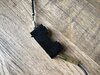
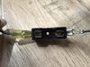
I bought like 100 of these https://www.digikey.com/en/products/detail/idec/AL6H-M14P-R/83446831618839072656.png

But from a different manuafacturer. They are like $25.00 each when your done. LED lamps, removeable different color lenses. You can label them under the lens. I had to replace nearly all of the other manufcturer's buttons/lamps because they changed to a new design where an O-ring held the button to the incadesent lamp and trapped the heat and the plastic got brittle. That was down right annoying.
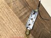
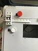
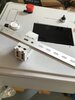
Most were indicator only. The switches I used were rotary and 22mm style.

Idec had different color LEDs for each lens and were AC/DC

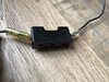
Industrial control panels are usually 24 VDC. I goofed and made mine 24 VAC. That was the first ones I did.

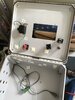
I basically built an alarm system with relay logic with one 3PDT relay per point. One contact was the NC alarm loop, one was the lighting circuit and the third was the latch. I didn't latch the panic buttons (local and exit doors). It probably was a good safety idea. No "alarm" was needed. The panel just had to quietly shut off some valves. No alarm history either.

I think the main mistake was not using "monitored contacts" which would have been a two wire system with an end of line resistor. A break in the line would have caused a trouble alarm.

The panel was upgraded once after it actually worked. el-cheap-o and "modified" air velocity sensors were upgraded and included a display. Hydrogen sensors that were not installed, were installed,. the gas involved in the "explosion" was hydrogen.

Then it got an expansion to enable another system. The other system got a PLC shutdown system with a UPS.
 
You could use "top hat brackets" to lift the DIN rail, they may be more stable than studding.
They are available for that exact purpose, but you can equally just make them from cut & bent metal strip.

These are rather shallow ones, but you can get (or make) them to whatever height you need.

TopHatBrackets_800.jpg
 
Status
Not open for further replies.

Latest threads

Back
Top