Continue to Site

Welcome to our site!

Electro Tech is an online community (with over 170,000 members) who enjoy talking about and building electronic circuits, projects and gadgets. To participate you need to register. Registration is free. Click here to register now.

  • Welcome to our site! Electro Tech is an online community (with over 170,000 members) who enjoy talking about and building electronic circuits, projects and gadgets. To participate you need to register. Registration is free. Click here to register now.

temperature intensity meter

Status
Not open for further replies.

4electros

New Member
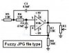
I've attached a circuit schematic for the temperaure intensity meter...
R1 is the PTC
the first 555 works as monostable so it triggers second 555 to produce Astable pulses with given frequency depending on the values(R3 and R3 and C4)

anyway i want to ask if i have to supply my second 555 with 5v supplier or not... cause in my circuit i've connect pin 3 of first 555 directly to pin 4 of the second 555 and didn't supply second 555...i've shorted pin 4 with pin 8 ( for the second 555)


want to know your viwpoints, and any suggestion will be appreciated!

thanks in advance!
 

Attachments

  • temperature_intensity_meter.jpg
    temperature_intensity_meter.jpg
    93.9 KB · Views: 632
you need to power ALL chips regardles if this is shown on diagram or not.
 
there:
 

Attachments

  • ckt_203.gif
    ckt_203.gif
    95 KB · Views: 619
...and U6.

you know you could also label things better, use larger connection dots, space components a bit more or move comments so they don't overlap.
i guess you did this just to create PCB so you didn't bother labeling thermistor either.
 
Also, please save schematics as a clear GIF or PNG file type. JPG schematics are very fuzzy. JPG is for photos.
 

Attachments

  • fuzzy_jpg.jpg
    fuzzy_jpg.jpg
    12.3 KB · Views: 580
Another question!
I'm so confused about supplying 7447 in my circuit... I know that i have to power it with Vcc on pin 16 and ground the pin 8 but what about the pins such as RB1 and LT (3,5), please help me!

what about some pins for other ICs in this circuit such as LS393 and 7408
any suggestion will be appriciated!
best regards!
 
good, those should answer any question.
First page of datasheet for 7447 says pin3 is LAMP TEST or LT.
page 4 has some notes (6 and 7) you might find interesting too.
now is any pin still problematic?
 
what about it? i'm not sure what is the question...

when you see line above signal (LT with dash above it for example) it means it's inverted signal. in other words, it's active when LOW.
if you connect pin3 (LT) to 0VDC or logical low, all display segments will be illuminated. if you connect to logic_1, display will work depending on other inputs. floating inputs in TTL are seen as logic_1.

same goes for RBI etc.
 
panic mode said:
what about it? i'm not sure what is the question...

when you see line above signal (LT with dash above it for example) it means it's inverted signal. in other words, it's active when LOW.
if you connect pin3 (LT) to 0VDC or logical low, all display segments will be illuminated. if you connect to logic_1, display will work depending on other inputs. floating inputs in TTL are seen as logic_1.

same goes for RBI etc.

well, i haven't connected the pins 3,5 to logic high so...7447 wouldn't depend on their inputs but as I said before when using simulation software like proteus that didn't affect the function of it!
 
Status
Not open for further replies.

Latest threads

New Articles From Microcontroller Tips

Back
Top