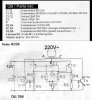
I have an old telescope, a rather large Cave 5” refractor, which has a small 115 volt 60hz synchronous motor on the polar shaft, and a reversible Hurst synchronous motor on the declination axis. As I am living in Australia stepping down mains power (50 Hz) will not work so I have been trying to build a frequency generator based around a kit sold by Kemo: Kit # B038 (http://www.kemo-electronic.com/en/bausaetze/b038/index.htm). The kit calls for a 10-0-10 center tap transformer for 240 volts out on the primary. I only need 115 volts so I looked for 10 volt center tap to 115 volts with no luck. I built up the kit with a 12-0-12 volt secondary. The output voltage shows only 60 volts AC on an analog panel meter, but 80 volts on a digital volt meter. The output frequency is adjustable over a wide range and does not change voltage appreciably. Output is a square wave and the kit says it is possible to place a capacitor across the output - I have not tried that yet. The small motor seems happy (but warm) running at this voltage, but the declination reversible motor runs erratically and does not develop enough power to move the heavy telescope reliably.
As a test I used a small inverter that plugs into a 12 volt car cig. lighter. It puts out 120 volts/60 hz and both motors run fine off of this adapter. It isn’t a solution because I need to control the speed of the motor on the polar shaft through frequency adjustment, but it does indicate to me that I need to find a way to increase the output voltage of the unit I built. I measured input voltage to secondary of the transformer at 8.5 volts (12 would obviously give me the correct voltage with my original transformer.)
The next experiment involved using a 15-0-15/240 volt transformer reasoning that if I put in half the voltage I should get half out…or in this case 120+ volts. This is the case but I’m unsure about the measured output voltage, and I’m rather worried about damaging the scope motors which are essentially non-replaceable. The analog panel meter reads 124 volts, but my digital volt meter reads 146 volts. Strangely when I compare analog and digital volt meter readings from the small car inverter they are very similar at 120 volts, and on my oscilloscope the vertical display is essentially the same for both inverters (i.e., leaving vertical gain unchanged when switching inverters – both driving the same load).
1. I don’t quite understand the differences in voltages that I’m reading. Will I ruin the motors running them at 124 (146 digital) volts?
2. Will placing a capacitor across the output help the situation in any way?
3. Where can I find a 10-0-10/115 volt 2amp transformer?
4. or if I go back to the original 12-0-12/117 volt transformer, is there a simple way I could add a stage of voltage amplification to boost the 8.5 volts available up to 12 volts?
5. Is it possible to modify any factory built inverters so that the frequency can be adjusted between 45-80hz?
Thanks very much for any help or suggestions offered!
(Yes!! If I had it to do over again I'd replace the synchronous motors with steppers, but I'm way too far into this project to start over!)