Electro Tech is an online community (with over 170,000 members) who enjoy talking about and building electronic circuits, projects and gadgets. To participate you need to register. Registration is free. Click here to register now.
Welcome to our site! Electro Tech is an online community (with over 170,000 members) who enjoy talking about and building electronic circuits, projects and gadgets. To participate you need to register. Registration is free. Click here to register now.
I have a 40 watt Radio Shack amplifier and a standard hard wire telephone with a one earphone and microphone headset. The headset has a 1/8th TRS plug. I want to amplify the phone. Any ideas on how to do it?
You need to use an audio isolation transformer between the phone's headphones jack and the amplifier's input so the phone line is still balanced and still cancels hum.
Get the transformer from an old modem.
You need to use an audio isolation transformer between the phone's headphones jack and the amplifier's input so the phone line is still balanced and still cancels hum.
Get the transformer from an old modem.
Dude! OK! I heard that before. I can go out and buy a modem card a Fry's. I ASSUME you mean the card that comes with every store bought pc like a Hewlett-Packard. It is the card that has the phone jack in it for dial-up type of web access. But which wires go where???????? I have all four poles from the Radio Shack RCA input jacks exposed and I have isolated the tip, ring and sleeve from the telephone headset jack. The ring and sleeve are sound and the tip is the microphone. I WANT TO DO THIS!!! I want a clear sound. I may buy another amplifier and increase to 80 watts. I can pay a little money. The audio engineering companies all laugh at me or want $1,000 minimum.
Oh Mannnnnnnnnnnn! What is up with you, dude? Steer me, don't veer me! You got an answer for me? I have a 40 watt Radio Shack amp and a hard wire phone and I need to HOW to hook it up and HOW to avoid squelch, hum and shrill whistles. Dude, I used caps to make a dynamic microphone work on the telephone line.
An audio isolation transformer has 2 wires in and 2 more wires out.
Both sides are the same so it doesn't matter if it is backwards.
Use an ohm-meter to measure which wires are in each coil.
The transformer connects to a line input (not a microphone input) on the amplifier.
The transformer has two coils. An ohm-meter will measure continuity from 1 wire to another wire to identify that those 2 wires are a coil. Then that coil can be the input. The other 2 wires can also be measured for continuity and be used for the output.
The transformer has two coils. An ohm-meter will measure continuity from 1 wire to another wire to identify that those 2 wires are a coil. Then that coil can be the input. The other 2 wires can also be measured for continuity and be used for the output.
The following took an aweful lot of time to find. There is almost nothing covering Audio Frequency Transformers. What you call "coils" the author calls "windings"?
"Audio-frequency (af) transformers are used in af circuits as coupling devices. Audio-frequency transformers are designed to operate at frequencies in the audio frequency spectrum (generally considered to be 15 Hz to 20kHz). They consist of a primary and a secondary winding wound on a laminated iron or steel core. Because these transformers are subjected to higher frequencies than are power transformers, special grades of steel such as silicon steel or special alloys of iron that have a very low hysteresis loss must be used for core material. These transformers usually have a greater number of turns in the secondary than in the primary; common step-up ratios being 1 to 2 or 1 to 4. With audio transformers the impedance of the primary and secondary windings is as important as the ratio of turns, since the transformer selected should have its impedance match the circuits to which it is connected."
I Wikied transformer a long time ago. Actually it has been so long that I forgot where I found the following:
"Audio-frequency (af) transformers are used in af circuits as coupling devices. Audio-frequency transformers are designed to operate at frequencies in the audio frequency spectrum (generally considered to be 15 Hz to 20kHz). They consist of a primary and a secondary winding wound on a laminated iron or steel core. Because these transformers are subjected to higher frequencies than are power transformers, special grades of steel such as silicon steel or special alloys of iron that have a very low hysteresis loss must be used for core material. These transformers usually have a greater number of turns in the secondary than in the primary; common step-up ratios being 1 to 2 or 1 to 4. With audio transformers the impedance of the primary and secondary windings is as important as the ratio of turns, since the transformer selected should have its impedance match the circuits to which it is connected."
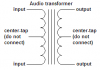
Here is the schematic of an audio transformer that you should have obtained from the manufacturer of your transformer.
It has an input coil (winding) and an output coil (winding).
The coils each have a connection at their center called a "center-tap" that you don't use. The coils are made of wire so their low resistance can be measured with an ohm-meter for continuity. The two coils are completely separate.
I have not purchased any audio transformers because I was told to obtain an "audio isolation transformer" from an old modem card found in a p.c. (Personal Computer) . Just how in hell I'm supposed to do that is beyond me. I don't even know what to look for. Do I desolder the damn thing off of the modem card??? I have the rotten luck of removing and discarding all four modem cards from all four of my p.c.!!! To demonstrate that we are talking about the same thing, the cards I removed and discarded had the female phone jack incorporated. I needed the slots so I removed and discarded the phone modem cards. I am trying to connect my standard hardwired phone to a 40 watt a.c. amplifier to amplify my phone conversation. Trust me when I say that I am aware of current legal ramifications and I will not divulge anything to anyone. I have all input/output RCA and TRS poles on my amp and phone attached to copper wire so the connections are ready to go. All I need to do is get the components and attach them. I noticed in a department store that an employee had a cell phone that was connected to the store p.a. system so all he had to do was press a button and he was heard over the p.a. I do not know if he could broadcast his phone conversation over the store p.a. But his system pretty much parallels what I am attempting to do.
An audio isolation transformer will isolate the ground on your amplifier from causing bad hum on the telephone line.
The cell phone uses air to isolate it from the telephone wires.
If you can't simply unsolder 4 pins on a transformer on a modem card then do gardening instead.
That's a bit harsh audioguru, how would he know what an audio isolation transformer looks like if he's never seen one before?
The kind of transformer used in a modem isn't as good as a high quality audio transformer, it'll only pass frequencies between 300Hz and 3kHz instead of 15Hz to 20kHz.
The kind of transformer used in a modem isn't as good as a high quality audio transformer, it'll only pass frequencies between 300Hz and 3kHz instead of 15Hz to 20kHz.
I measured the horrible frequency response of one telephone line to another telephone line:
3kHz was down about -12dB. I complained to BELL and they said it was normal. Their limit is -7.5dB one-way which is -15dB round trip.
I didn't bother measuring the low frequencies because there weren't any at the receiving end.
The response was flat from about 850Hz to about 950Hz.
For a few years I installed and programmed (DSP acoustical echo cancellers)high quality boardroom telephone conferencing systems. I made a transmit equalizer that had a peak of +12dB at 3.5kHz. Every time I demo'd my equalizer the people said the sound was much crisper and clearer and it was sold.
The guy in the store probably had a paging amplifier (5W) attached to his phone system. If you're not concerned about legal ramifications, you can use capacitors to isolate the line. If you don't want shrieks and whistles get a frequency shifter or cut the mic off.
The best thing would be to connect a 1:1 transformer at the points of Reciver (Also called ear piece) at the instrument 4 way cable comming to handset. use the secondary with a resistive divider for matching purposes)
At this point the side tone is well suppressed-thus the microphone signals will be minimal.
This site uses cookies to help personalise content, tailor your experience and to keep you logged in if you register.
By continuing to use this site, you are consenting to our use of cookies.