Continue to Site

Welcome to our site!

Electro Tech is an online community (with over 170,000 members) who enjoy talking about and building electronic circuits, projects and gadgets. To participate you need to register. Registration is free. Click here to register now.

  • Welcome to our site! Electro Tech is an online community (with over 170,000 members) who enjoy talking about and building electronic circuits, projects and gadgets. To participate you need to register. Registration is free. Click here to register now.

Telephone CutBox circuit help

Status
Not open for further replies.

Qix

New Member
I need help with designing a circuit to help me in cutting customers telephones lines from one central office to another. The basic idea is to be able to hear the ANI (automated number identification) from the test line on my talk line. My TALK LINE is a normal phone connection to a facilities tech.. I want to dial the ANI with my DIALER on the TEST LINE and be able to hear the number call-out from that line on my talk line.

I have a working circuit I am using now but the volume is very low coming from the test line. I am using .01 uf caps (200v) as C1 and C2 with a 600ohm 1:1 isolation transformer. Can someone suggest the correct cap values which would give the loudest audio from the test line to my talk pair or suggest a better simple circuit.
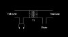
My circuit:

**broken link removed**

I may be way off track but my reasoning behind this circuit design is to use the isolation transformer to separate the power sources from two central offices and the two capacitors to block DC current to NOT take the phones off hook.

Line voltages are 45v dc on-hook, 5-10v dc off-hook and ringing volts spiking to aprox 90v vrms 20hz.

I am not worried about voltage or current protection anywhere in this circuit , except the caps and transformer, as the end equipment are telco test sets and are already protected..

Any help would be appreciated..
Thanks, MarkW
 
I can see what you want, and it is a basic bridging circuit. But your problem is not with the caps, it is with the way the coil is arranged in the circuit. You have the coil wired in parallel with both the test set side, and the dialer side. These two sets already act like a basic telephone unit and all the line current (both the DC and AC voice component) flow thru them not leaving much left to flow thru the bridging coil. Try inserting the coil legs in series with both sides of the line and it should work just fine (remove the caps). You can add a Double pole single throw switch across one/both sides of the coil to shunt it out when you do not want the lines bridged.

Dialtone
 

Attachments

  • Bridge_202.jpg
    Bridge_202.jpg
    8.3 KB · Views: 629
Dialtone,

Thanks for the suggestions. It may make the volume louder but the effects would not be what I need.

Having no capacitor means DC will pass through the circuit. This will take the phone off hook when I clip on a customers line. I need to monitor the line before I dial the ANI just in case it is in use. Shunting the transformer would just take the customer's phone off hook when I clip on it and I would not hear if it was busy or not.

I usally am on a customer's line for about 10 seconds. Just enough time to listen for dialtone, autodial the ANI and listen for the number returned. This sequence is done on anywhere from 100 to 300 lines a day depending if I'm working on a telephone pole or under ground in a man-hole. :)

I wonder is using a 1:10 transformer (test-line:test-set) would make a differance?
 
You did not state exactly what equipment you were using for each side of the line (or how it works for that matter). I assumed both the talk and dial mechanism were standard butt sets that have a monitor mode switch. If that is true, then the circuit I proposed will work. In monitor mode, insufficient current will flow thru the butt sets to complete the circuit and take the line off hook, untill you switch it to talk/dial mode. Let me know it that is or is not true/ then I can help further.
Dialtone
 
Dialtone said:
You did not state exactly what equipment you were using for each side of the line (or how it works for that matter). I assumed both the talk and dial mechanism were standard butt sets that have a monitor mode switch. If that is true, then the circuit I proposed will work. In monitor mode, insufficient current will flow thru the butt sets to complete the circuit and take the line off hook, untill you switch it to talk/dial mode. Let me know it that is or is not true/ then I can help further.
Dialtone

Yes, I am using a standard standard butt-in test set, with monitor/offhook switch, as the DIALER. I am using a Supra Splicer's headset to communicate with the facilities tech. The Butt set is usually hanging at arms length with the dial pad facing me. I only use this set for taking the test line off hook and dialing. The Supra is the only equipment I listen and talk into. I have a bridging clip hooked in parallel with the butt set which I clip on the customer's line with. I updated the image up on my first message to more reflect what the connections look like.

You are correct on the phone line staying in an idle state when the dialer's monitor switch is on. But little current also flows through the coil in this state which gives little volume on the Supra headset. I can not hear if the line is in use.
 
Dialtone,

Your circuit worked perfectly after I replaced the defective isolation transformer. Hooked a spare one up in series with the head set and the dial set and everything is loud and clear.

I can even hear if the line is in use with the dial set in monitor mode. Better still, the series circuit works with dialing P-Phones too. :)

Thanks a bunch for the circuit help.
 
Glad I was able to be of some assistance.
Guess I did not waste those 30 years in the phone business after all.
Dialtone (retired)
 
I have 10 more years to go before I can enjoy retirement. Started out splicing, then to I&R, back to splicing, did 4 years as a DSL tech and here I am back to splicing. (Copper of course. I can do it, but I hate fibre)

What did you do in those 30 years in the phone business?
 
Started out in switching equipment installation with Western Electric- AT&T Network Systems and finally Lucent Tech. I have seen almost all versions of C.O. switches from step by step thru the current digital systems. Looks like I will miss out on the next gen IP switches but will leave that for the younger crowd if any are still left.

Dialtone
 
Status
Not open for further replies.

Latest threads

New Articles From Microcontroller Tips

Back
Top