Continue to Site

Welcome to our site!

Electro Tech is an online community (with over 170,000 members) who enjoy talking about and building electronic circuits, projects and gadgets. To participate you need to register. Registration is free. Click here to register now.

  • Welcome to our site! Electro Tech is an online community (with over 170,000 members) who enjoy talking about and building electronic circuits, projects and gadgets. To participate you need to register. Registration is free. Click here to register now.

TDA1557 issue

Status
Not open for further replies.

nchaaa

New Member
Hi all,

I needed a simple stereo amplifier, working on a 12Vdc power supply, and naturally choose TDA1557 audio amplifier.
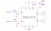
The typical circuit is very simple. I have followed the datasheet carefully, but my circuit does not work:
- when the pin12 (Vref) is not connected, the circuit starts to "pump" a lot of current (more than 2 amps) , and although there is no input signal, a loud random noise happens on the speaker
- when i connect this pin to the GND, supplied current seems more reasonnible, but nothing is happening (input signal is not amplified, no output signal).

Can someone help me ?
 
The datasheet doesn't have details about the REF and MUTE pins.

The test circuit shows the REF pin not connected. I think it needs a capacitor to ground. Since you grounded the REF then maybe you broke the IC.

The MUTE pin is also not connected. I think it mutes when low and turns on the amps when high (more than 8.5V).
 
Okay, i will try with a capacitor to ground for the Vref pin.
For the pin mute, yes, it power-on the IC when it is high (let's say Vcc)
 
Hi nchaaa,

I am sure that your circuit will work even if you do not connect the Vref pin(let it free)

I guess that the problem is due to 'MUTE' and STAND-BY switch(pin 11).
connect that pin to VCC through a 82K resistor and with a 22uF capacitor to ground.
I am pretty sure your problem would be solved if you do so;)
 
Hi wizard,

If I made no mistake, this RC combination gives a 1.8s power-on delay.

Why do you think this will solves my problem ? Have you experimented this solution yourself ?
I really hope it will solve my issue anyway...
I will try this this monday, cause my circuit is at my workplace, so no test this WE :(
 
Hey nchaaa,

I noticed that you told that the circuit draws 2 Amps Without connecting the Vref.

I have made several amplifiers using that chip. The Vreff pin was not connected for none of them and I had NO problem at all (I used two of those amplifiers in a home made radio and they worked just fine). If your circuit draws 2 amps without any input so maybe your chip is fried? or maybe you have a problem with wrong wiring?

If you are sure that your chip and wiring are fine, just let me know to put my
schematic here(that chip has just 7 or 8 components for biasing, so you can handle it easily)

besides, yes that RC circuit is there for producing a small delay, but you have to bias the MUTE pin with VCC (the resistor does that job too) and don't use the said capacitor to get any delay(that's what I have done for one of my amplifiers)
 
hi nchaaa

i did that a year ago also on a test board and never worked well because it needs good wiring and a common ground place..

print this pcb and try it...

it doesn't matter that it says tda1553q it's almost the same with the tda1557qyou just don't put the c4 capacitor...

if you don't understand something ask me.
 

Attachments

  • tda1553q_amp_495.zip
    21.2 KB · Views: 515
Hi,

I had a look at your PCB, and understood all (3 components, easy).
you are right, it seems compatible with 1557Q, so I will try this on Monday.
I will then let you know the results.
 
@wizard:
my pinning seems ok, i am of course not sure about the IC, maybe he is fried.
can you send me ypur lyaout?

@whiz115:
i have tried with your schematic and by adding a large ground plane, but still not working...

If i make a new purchase of Ics, which one would you adivsed me to take ? stereo and around 20W is enough for me (12Vcc supply is a must)
 
@whiz115:
i have tried with your schematic and by adding a large ground plane, but still not working...

Hi...

did you connected the power supply and your audio source with in the correct way?

have you used a jumper for the mute?

if yes then probably your IC is burned and try with another.
 
You must read a datasheet carefully when it is for a car radio amplifier.
The TDA1557 and most other amplifiers are rated at 22 Whats per channel into 4 ohms with a 14.4V supply. Whats are produced when the volume control is turned up way too high so the output is a horribly distorted square-wave.
The TDA1557 is rated at 12 Watts RMS per channel into 4 ohms at clipping with a 13.2V supply. When the supply is only 12V then the output power is much less.
When the speakers are 8 ohms then the power is halved.
 
Last edited:
@wizard:
my pinning seems ok, i am of course not sure about the IC, maybe he is fried.
can you send me ypur lyaout?

SO I am suspect to the IC itself, please replace it with a new one.

This is my circuitry (I have drew it in PSPICE ):
 

Attachments

  • TDA1557Q.png
    TDA1557Q.png
    17.8 KB · Views: 3,282
The input resistance of the TDA1557 is 30 k ohms so your HUGE 4.7uF input capacitor will produce an output down to 1.1Hz. Amazing.
 
Don't use electrolic caps as the input capacitor. I once did this with that amp IC and it caused it to do all sorts of strange stuff.Use poliester and such caps for that. The Vref cap is recommended for single eded mode configuration to reduce noise. But you must be using bridge configuration since it doubles the power and halfs the 4 channels in to 2
 
Hi,

I have read carefully datasheet, triple-checked wiring, and this amplifier is still not working.
So I have ordered new IC, but this time I will go with TDA1554. I guess the silicium design is not very different from the TDA1557, but it does not have this Vref pin, which from the beginning, i am wondering what this pin is for, and for which i did not get clear info on what to do with it.

Do you guys have some advices to give for this TDA1554?
 
The input resistance of the TDA1557 is 30 k ohms so your HUGE 4.7uF input capacitor will produce an output down to 1.1Hz. Amazing.

Well, I never used a 4.7u cap on any of those amplifiers by myself. I never exceeded more than 0.1u for that.
It will work with that cap though.


Don't use electrolic caps as the input capacitor. I once did this with that amp IC and it caused it to do all sorts of strange stuff.Use poliester and such caps for that. The Vref cap is recommended for single eded mode configuration to reduce noise. But you must be using bridge configuration since it doubles the power and halfs the 4 channels in to 2

He can use a 104 ceramic cap like I did.

Did you ever use it as a bridged amplifier?
As I know it is not possible to bridge a BRIDGED amplifier twice!?
 
Last edited:
Hi,

I have read carefully datasheet, triple-checked wiring, and this amplifier is still not working.
So I have ordered new IC, but this time I will go with TDA1554. I guess the silicium design is not very different from the TDA1557, but it does not have this Vref pin, which from the beginning, i am wondering what this pin is for, and for which i did not get clear info on what to do with it.

Do you guys have some advices to give for this TDA1554?

i was also wondering and i was creating new topics on forums so i can learn...
don't waste your time thinking what to do with the Vref, this amplifier is very simple.

recomended value for the input capacitors is 220nF and a 100nF for decoupling on the power rails... assuming that your power supply has
enough smoothing capacitance.

the pcb i posted makes your life easy, but if you want to go on with the TDA1554 it's your decision.
 
Status
Not open for further replies.

Latest threads

Back
Top