Continue to Site

Welcome to our site!

Electro Tech is an online community (with over 170,000 members) who enjoy talking about and building electronic circuits, projects and gadgets. To participate you need to register. Registration is free. Click here to register now.

  • Welcome to our site! Electro Tech is an online community (with over 170,000 members) who enjoy talking about and building electronic circuits, projects and gadgets. To participate you need to register. Registration is free. Click here to register now.

TDA 2050 Amplifier

Status
Not open for further replies.

Injac93

New Member
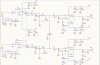
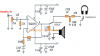
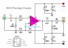
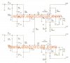
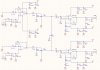
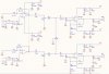
Hello, i lets say "designed" this circuit, just took parts from other projcets datasheets, and kinda mixed it all in to create one pre-amp with TL072 and an amp with TDA2050. I have speakers that are about 20W each channel. I dont need any bass balance, treble etc in the circuit, i just want to amplify the signal from the input so i get on the output around 20V. The crossovers i will do in the speaker box. Used P1 as the balance between left and right channel, and P2,P3 for the volume control. My question is, will this circuit work, since its my first project of this kind, im sure i have some major failures in the design, would someone look up the circuit and modify it if needed so it would work good. I dont need it to maximum perfection, just so it doesnt have large distortions and it will do its job. I just want to make a small Hi Fi. Thank you in advance :)
 

Attachments

  • AMP.jpg
    AMP.jpg
    335 KB · Views: 215
In input the 4k7 resistor and 100nF capasitor form ~340Hz low pass filter.
Change the capasitor to 1.5nF
 
All of this applies to both channels.

470 farads seems a bit large for power supply decoupling of a standard opamp. Reduce C19 and C21 to 10 uF.

What is the reason for R13 and R14? Your gain of 12 preamp is not gain of less than 6. If you are worried about P1 putting a short to GND on one opamp when the balance is all the way to one side, put a 10K resistor in series with the P2 wiper before it connects to P1.

The R2-C2 high pass filter is at 10.6 Hz. For a flatter low end response and less phase shift at low bass notes, increase C2 to 47 uF.

For better parts commonality, use 47 uF for the six decoupling electrolytics.

What is the purpose of C4?

ak
 
Well as i said i looked from other projcets the circuit shematics and tried to combine them see what every circuit needs, i dont have that much knowledge whats exactly where happening but here are the circuits i combined mine from, what would you modify from these. Some of the low high pass filters are from datasheets that also confuse me. Thank you for your patience :)
 

Attachments

  • 32 watt.png
    32 watt.png
    108.1 KB · Views: 819
  • HiFi PreAmp Circuit Schematic.jpg
    HiFi PreAmp Circuit Schematic.jpg
    111.2 KB · Views: 521
  • the-50W-+-50W-stereo-power-amplifier-circuit-using-TDA2050.jpg
    the-50W-+-50W-stereo-power-amplifier-circuit-using-TDA2050.jpg
    180.8 KB · Views: 175
  • Pre-amp-Hifi-circuit2.gif
    Pre-amp-Hifi-circuit2.gif
    7.3 KB · Views: 185
The power amp section looks like it is lifted from the datasheet. That is a good circuit to keep, although I still think the low frequency corner can be moved. ST recommends 470 uF decoupling caps, so strike my previous suggestion. Audio power amp parts are extremely sensitive to decoupling cap value and placement.
https://www.st.com/resource/en/datasheet/CD00000131.pdf

Besides the other suggestions, delete C4 from the volume pots. It introduces a lowpass filter whose corner frequency changes as the volume is adjusted.

I suggest you make the changes to your schematic and post the updated version.

ak
 
Ok so here are with all the modifications, i calculated the filters low/high pass etc, its all in range between ~7Hz to 22kHz, now the only thing if you can check are those values good i mean i have 1.5nF and a 4k7 resistor at the input of preamp, should i maybe reduce the value of the resistor and increase the value of capacitor is 1.5nF too low? If you know what i mean, theoreticly i know that the values are best when they are kinda in the middle so the resistor is not to high and capacitor too low and the other way around. If you understand what i said :D

My other question is also if this is the final circuit. What kind of capacitors should i use for which part of the circuit i know from the supply like C3, C6, C10, C13, C19 and C21 i should use electrolit, but for the others im not sure, should i go for electrolit, block, mayler, ceramic etc. And what to those kind of capacitors bring to this circuit, what changes when they are diffrent kind (just for my knowledge in the future). Im very thankful for you patience and help. Thank you once again :)
 

Attachments

  • AMP.jpg
    AMP.jpg
    207.2 KB · Views: 200
You can delete R14 and R20.

Again, add a resistor between the wipers of P2/P3 and the left sides of C1/C8 where they connect to P1. You don't want P1 to present a dead short to GND to either opamp when the balance control is all the way to one side.

As above, change C3, C6, C10, C13 back to 470 uF.

The non-electrolytic caps can be ceramic, stacked metal film, polyester, whatever.

ak
 
The total gain is 400 times! Is it for a microphone ?
C15 and C17 cut high audio frequencies that some people like to hear. Why cut them?
R9, R15, R14 and R20 are useless and can be removed.
I hope your inputs have no DC on them since the preamp has no input coupling capacitors.
 
Ceramic capacitors are microphonic and produce noises from vibrations (maybe the sound from the speakers to cause feedback!) and cause distortion because their capacitance changes with voltage. Use plastic film coupling capacitors for values of 1uF and less, electrolytic for above. The 100nF power supply capacitors, C5 and C12 can be ceramic.
 
R9, R15, R14 and R20 are useless and can be removed.
R14 and R20 prevent the balance pot from presenting the preamps with a dead short to GND when all the way to one side. They could be smaller, but I wouldn't go below 2.2K.

ak
 
There is nothing wrong with shorting the (+) input of an opamp that has Jfet inputs to ground. Most volume controls short the input to ground when it is turned down.
 
P1 has the potential to place a dead short to GND on the *outputs* of the TL072 opamps through C16 and C18.

ak
 
Isnt C15 and C17 of 1.5nF with the resistor of 4.7k equal to 22kHz, i calculated and its a good high frequency cut? I was going for a 10 times gain on the preamp, and i used datasheet circuit for TDA2050, that gains 32 times, i have an input from the 3mm jack around 100mV and out at max 21V on the speakers? Should i reduce the gain of the preamp so i get a total of 200gain in preamp and amp? Also im not sure but i think i will have dc input, my project was to play from phone to speakers, what kinda and what value should i put the coupling capacitors? Isnt C15 and C17 coupling cap for dc input, if not where should i attach them, sry if im low knowledge at this but just want to be sure im doing it right and understand what im doing. Thank you
 
If the cutoff frequency is at 22kHz then it is reduced (-3dB) which muffles high audio frequencies a little and the cut starts at about 6.6kHz. Don't you want flat response to 20kHz? Then the -3dB cutoff should be about 66kHz.
If the amplifier output is 21V RMS then it is 59.4V peak-to-peak that needs a power supply that is about plus and minus 34V which is much more than your plus and minus 21V. Your output of 21V RMS is a squarewave full of clipping.

You will have high frequency oscillation (and the resulting distortion) if the circuit is built on a solderless breadboard with its stray capacitance between all the rows of contacts and wires.
The TL072 will oscillate if it directly drives the capacitance of a shielded cable. It should have a 100 ohm resistor in series with the cable for isolation.
 
Yes it is on a solderless board. These speakers that im doing on were with this power supply of 21V so i guess im gonna stick to it since i dont have another one. If i understood you corectly i should increase the cut off high filter to around 66kHz? What about the lower frequency? Where should i start it? And i didnt quite understand what do you mean by "directly drives the capacitance of a shielded cable", where should i put a 100 ohm resistor, to +vcc and -vcc of the tl072?
 
A solderless breadboard is no good for an audio amplifier circuit. Use it for LEDs or other low current low frequency or DC signals.
For the response to be flat to 20kHz then the cutoff should be 66kHz but the old TDA2050 can only barely go that high. So you do not need a high frequency cutoff.
For the response to be flat down to 20Hz then the low frequency cutoff should be about 6Hz for one RC but should be lower for more than one RC coupling. Your circuit has a few RC couplings.

A shielded cable has capacitance. If an opamp has it connected to its output then the capacitance of the cable causes a phase shift that causes oscillation. Adding a 100 ohm resistor in series between the output of the opamp circuit and the shielded cable isolates them.
 
Ok, thank you. If it was you who would go with tl072 and tda2050, how would you build it, would you use a circuit like this or different. I would really apriciate it, if you made some scheme or something, just to get a visual. Thank you
 
Status
Not open for further replies.

Latest threads

New Articles From Microcontroller Tips

Back
Top