Continue to Site

Welcome to our site!

Electro Tech is an online community (with over 170,000 members) who enjoy talking about and building electronic circuits, projects and gadgets. To participate you need to register. Registration is free. Click here to register now.

  • Welcome to our site! Electro Tech is an online community (with over 170,000 members) who enjoy talking about and building electronic circuits, projects and gadgets. To participate you need to register. Registration is free. Click here to register now.

Symbol Identification

Status
Not open for further replies.

ACharnley

Member
It's in a Microchip document, some type of current sensor. I've inverted the part in question.

Thanks, Andrew
 

Attachments

  • Screenshot_2019-04-17_21-50-19.png
    Screenshot_2019-04-17_21-50-19.png
    30.5 KB · Views: 129
I would say it is an insulated loop of wire ... not a shield, but just a loop to "capacitively" pickup any back emf from the inductor to the Op-Amp trigger circuit.
 
The way I see it is a generic symbol for current sensing. The uC will probably expect a 0 to 5V (3.3?) analog signal representing that current.
A high-side current sense amplifier and a shunt resistor would be a typical implementation of that.
 
What's odd is the document is all about being able to do the complete process using Microchip's MCU, so I doubt it expects another chip.

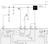
The input goes into the MCU's built-in comparator, the voltage of which is divided by the Rgs of the lower FET. If the buck/boost is working with a higher voltage it needs a resistor and possibly a zener. Max comparator impedence is 10k, but 10k and ~100ohm (RGS) leaves little for the comparator to do it's job..

Regards,

Andrew
 
Microchip support reckon it's just an error and should be a wired connection. I'm very doubtful on this - assuming the Buck works above the PIC's operating voltage that won't end well.
 
It doesn't make sense to measure the current there. The common point between the two MOSFETs will go below zero when the body diode of the low side MOSFET is conducting, so that is when the low side MOSFET should be turned on to reduce the losses. The current will still be flowing in the same direction where the odd symbol is.

Other circuits in that datasheet have a potential divider. I think that is what should be used. The symbol could also mean that there is a capacitive connection. The rapid change in voltage as the high side MOSFET turns off could be enough to switch the comparator.

I agreed that a wired connection and a high voltage input will destroy the PIC.
 
In text books I have that is a "current probe".
The current can be measured in many places.
This is a classic current mode power supply. (current mode verses voltage mode)
1555603051026.png


From link in post #5. When the voltage on "CMP3 negative" gets too high it causes the MOSFET to turn off. In current mode PWM the MOSFET is turned off when the current reaches the required level.
1555602858043.png
 
Measuring below the FET using a current sense won't work for an ideal diode. When current is sensed (aka backflow) the FET is turned off, which stops the current which turns the FET on. Oscillation in other words.

Measuring after the inductor won't work either as the voltage won't fall to zero (assuming capacitive load).

As usual I have several threads on the go converging into the same topic :). I worked out that for the PIC16F1769 comparator characteristics, a 100V input would result in a 2K resistor minimum (50mA pin sink), which for a 100mOhm FET would require a 500V input for sense to work. From this I derived resistor based detection is not possible, at least, not without a comparator with a very fine resolution and a very accurate resistor.
 
PS) I have a thread on the microchip forum about this diagram and and clarified the comparator inverting can't be ground
 
Maybe it's supposed to work like an antenna
 
From Microchip...

"This is a generic current sense symbol. There should be a component there. A differential current sense amplifier would do the work or a current sense transformer. The MCP6C02 current sense amplifier can be used or a current sense transformer such as the one done on the CIP Hybrid Power Starter Kit."
 
Status
Not open for further replies.

Latest threads

New Articles From Microcontroller Tips

Back
Top