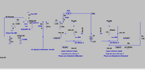
Page 5 of the MCR datasheet shows what is missing - the diode across the inductive load - in this case across terminals 85 & 86 of the relays.
I would be adding those but use 1N4004 or better diodes instead of 1N4148's.
As per Nigel's suggestion, a 1W zener instead of the original would be a good idea.
They sound like hefty magnetic clutches, so possible they can be putting some big spikes on the supply line.
Rigorous testing would be a good idea after repairing this one with a load 2-3 times what is normally expected.