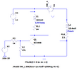
The attached pdf shows the various forms of contact suppression, you will be looking at the first one and calculating the component values is shown (a resistor and a capacitor).
For the capacitor, X2 Metallized Polypropylene Film Capacitor like this
https://www.altronics.com.au/p/r3137a-1.0uf-x2-pcb-mains-suppression-capacitor/ and for the resistor 1W carbon or metal film should be fine for testing (do not use the 5w wirewound types).
Going by the calculations and the current you mentioned previously, the resistor would be 12Ω and the capacitor ~4μF - may mean paralleling several capacitors depending on what values you can source.