Continue to Site

Welcome to our site!

Electro Tech is an online community (with over 170,000 members) who enjoy talking about and building electronic circuits, projects and gadgets. To participate you need to register. Registration is free. Click here to register now.

  • Welcome to our site! Electro Tech is an online community (with over 170,000 members) who enjoy talking about and building electronic circuits, projects and gadgets. To participate you need to register. Registration is free. Click here to register now.

Switching serial DATA between two sources

Status
Not open for further replies.

camerart

Well-Known Member
Hi,
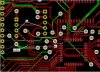
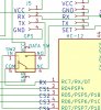
I have a PCB where two serial DATA SOURCES need to be alternatively switched to an RX INPUT.

I used a MAX4644 for this.

It appears to switch ok,when series testing, but when there's DATA on either source the two sources appear to merge.

Any thoughts please?
Camerart.
 
Do you have a load resistor, eg. a pullup, on the MCU RX input pin?
That may be needed to avoid stray inputs or noise.

I'd try something like a 10K and see if that has any effect. If you are still seeing both, it suggests a faulty device or wiring problem.
 
Hi,
The signals are 3.3V RS232 e,g, NMEA sentences from a GPS module.

Here's a section from the PCB drawing.

I'll try a 10K resistor.

I'll look at the analogue type switches, if the MAX4644 doesn't look suitable.

C
 

Attachments

  • Serial switch.jpg
    Serial switch.jpg
    461.5 KB · Views: 211
  • 2 to 1.jpg
    2 to 1.jpg
    126 KB · Views: 194
The connector to the left of the switch IC shows a 5V power connection; if the data signal exceeds the 3.3V supply to the switch it will almost certainly malfunction.

You may need a resistive divider first to keep the signal within a suitable voltage range.
 
What do you mean by "appear to merge"?
Hi D,
1st, Do you agree with 'I' that this switch isn't suitable or is it ok?

Before connecting the HC-12 radio and GPS to the 2x INPUTs, I tested the switch and it switched ok.

With both modules connected and running:
When switched to the GPS, it looks as if the HC-12 is not connected.
When switched to the HC-12 the GPS both signals appear at the PIC INPUT PIN.

C.
 
The connector to the left of the switch IC shows a 5V power connection; if the data signal exceeds the 3.3V supply to the switch it will almost certainly malfunction.

You may need a resistive divider first to keep the signal within a suitable voltage range.
Hi R,
The 5V is the supply voltage of the GPS then regulated to 3.3V which is the output voltage, all other modules are 3.3V.

Reading the MAX4644 D/S it looks as though a 5V supply may help. If it was powered at 5V would the 3.3V signal switch it?
C.
 
Hi D,
1st, Do you agree with 'I' that this switch isn't suitable or is it ok?

Before connecting the HC-12 radio and GPS to the 2x INPUTs, I tested the switch and it switched ok.

With both modules connected and running:
When switched to the GPS, it looks as if the HC-12 is not connected.
When switched to the HC-12 the GPS both signals appear at the PIC INPUT PIN.

C.
I personally don't see an obvious issue with using that switch.

But cameraart is right. If your gps is putting 5V into the switch and the switch is being powered by 3.3V, the ESD clamp diodes will conduct and possibly cause the behaviour you are seeing.
 
I personally don't see an obvious issue with using that switch.

But cameraart is right. If your gps is putting 5V into the switch and the switch is being powered by 3.3V, the ESD clamp diodes will conduct and possibly cause the behaviour you are seeing.
Hi D,

Ok, I'll carry on with this switch.

Correction: The GPS is supplied by 5V, but it's output is 3.3V as all the other modules on the circuit.
I did ask what would happen if the switch is powered by 5V and switched by 3.3V?
C.
 
Can you test by applying DC signals to one side that are 3.3V and 5V and see what happens? Or 3.3V and one of your modules?

Did you decouple the IC?
 
Hi,
First test with my new/old scope, and I'm still getting used to it.

The switch input looks like it's switching ok 0-3.3V
Both inputs looks ok, and again 0-3.3V signal.

It look as though the GPS signal is showing occasionally at the RX PIN when HC-12 is selected.

I'll add decoupling caps to the 3.3V PIN and the switch PIN (Is this correct?), then re-test. Is this what's suggested?

C.
 
You should have those decoupling caps either way. Not sure if they are responsible for your issues though.
 
Either way:
-if the caps are causing the problem
-if the caps are not causing the problem
 
Hi,
I added 104 caps to the 3.3v and the switch track, also changed to 5V supply for the switch. It seems better, but it looks like it's not perfect, although it's not easy to see.

Could it be the PIC internal clock? I received 8MHz crystals today.

C.
 
Status
Not open for further replies.

Latest threads

New Articles From Microcontroller Tips

Back
Top