camerart
Well-Known Member
Hi,
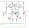
I have been using this design of H-Bridge for years quite successfully, only switching 1 and 4 or 2 and 3 on and off in pairs. I am now trying to use PWM, by switching PWM to 1 and 4 or 2 and 3. I have been getting odd results, because the settings for PWM need to be higher than I would have thought to start the motor. Thinking the problem could be a difference in ON/OFF timing between the transistor switched FETs and the directly switched FETs or the different characteristics of P and N FETs or both, giving misaligned square waves, I tried different switching. The stop/forward/reverse/stop sequence: ALL OFF>>1 ON then PWM 4>>ALL OFF>>2 ON then PWM 3>>ALL OFF. This gave good results.
Can someone confirm that this is a good way of switching please?
Camerart.