Continue to Site

Welcome to our site!

Electro Tech is an online community (with over 170,000 members) who enjoy talking about and building electronic circuits, projects and gadgets. To participate you need to register. Registration is free. Click here to register now.

  • Welcome to our site! Electro Tech is an online community (with over 170,000 members) who enjoy talking about and building electronic circuits, projects and gadgets. To participate you need to register. Registration is free. Click here to register now.

Looking for suggestions on how to approach switching power to a series of EM Coils along a rail (EM Launcher)

EHTDesigner

New Member
I'm going to do a search on this question as I've seen some similar questions answered.

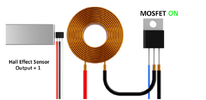
I'm starting a project that I've seen videos of and would like to make some changes to it for my purposes. It's an Electromagnetic Launcher. A photo of one of the coils is below. Let's say there would be 10 of these coils along a rail. There's a hall effect sensor that turns on a MOSFET energizing the coil when a magnet comes close to the hall effect sensor. The result is the field of the coil will pull the magnet towards the coil's center propelling the magnet forward. However once the magnet reaches the other side of the coil, the field present will pull the magnet back to the center of the coil, thus stopping the magnet from moving forward. What suggestions do you have to reverse the polarity to the coil when the magnet reaches the center of the coil? I was considering an H-Bridge but cant quite see how to use that in conjunction with the MOSFET. If I have 10 coils in a row, do I need 10 separate circuits or can there be a way to turn on power to the other coils. Power is on to the coil only when the magnet passes the hall effect sensors
 

Attachments

  • 1717686345260.png
    1717686345260.png
    127.8 KB · Views: 120
An H-bridge is usually 4 MOSFETs. Two are tuned on to energise the load in one direction, the other two are turned on to energise the load in the other direction.

You will need 10 circuits.

You will probably need to have H-bridges to reverse the current quickly. You will also need large voltages to start and stop the current quickly.

It may be possible to have only 6 H-bridges to run 10 coils if you only need to run one at a time. Here is how three motors can be run from two H-bridges, and that idea can be extended.

1717691207257.png

(That is from the data sheet of a VNH5019A-E if you want to know more. The extra MOSFET is for reverse polarity protection)

The first H-bridge can run one load in either direction, and each additional H-bridge adds two more loads. So 6 H-bridges could run 11 loads in either direction if you only ever needed to run one at a time.
 
I looked at the data sheet. Would I be able to just connect the hall effect sensors to the two inputs to operate this? Sensor 1 would connect to IN A. when Sensor 1 turns off, then Sensor 2 connected to IN B will turn on

If needed, could I replace the motors in the Figure 15 with power MOSFETS to drive higher current coils or motors than the 12A max from this H-Bridge?
 
As long as the voltage is not too high, you could use BTS7960 half bridge driver ICs or full bridge modules - they are rated at 43A.

These modules with two ICs to make a full bridge are readily available from various places:

Jut be aware that a common diagram for these shows them with a built-in 5V regulator.. The typical modules do not have that, the logic supply pin is an input & you need an external 5V or 3.3V supply.
 
This is a synchronous linear motor. It is useful to understand how the magnetics of BLDC rotary motor couples and translate it to linear acceleration.

Each coil force is now like a linear solenoid and increases with the length of the coil and the magnetic material.
What is the sum of these magnetic lengths compared to the path length?

The slide bearings must have very low friction since it is essentially coasting between these magnetic force gaps.

The full bridge must reverse the current in the coil precisely when the centre of the magnet moves past the centre of the coil. Any position error will have the negative consequence of a reverse force during that transition. A deadtime spans a longer distance at slower speeds.

It's not a Large Hadron Collider but there is more to it than counting coils and bridges.
 
Thanks Tony, Diver300.
Considering the dual H-Bridge in Figure 15. If I connect electromagnets (which are the coils) as the motor M1, M1 and M3, is there sufficient voltage and current from the H-Bridge to drive the electromagnets? All 3 a the same time? Drive in one direction, then drive in the other direction? Bi Polar Latching Hall Effect Sensor 1 connected to INa of both Bridges, that would turn on and off the 3 coils in the "forward" direction. Bi Polar Latching Hall Effect Sensor 2 connected to INb of both bridges would turn on and off the 3 coils in the "reverse" direction.

I understand 12A continuous is the spec for the H-Bridges

So is 12 A is provided by configuration in Fig 15. For the electromagnet below would I simply connect 3 of these "Coils" to the H-Bridge and expect them to be powered by the H-Bridge?

I'm having difficulty seeing that this IC would be able to provide that much power or current to the coils/electromagnets.


1720795820490.png
 
That electromagnet appears to be this style:
Heschen Electromagnet Magnet Solenoid P80/38, OD: 80mm, DC 24V, 100Kg/220 lb

I cannot find any listings that give either the current rating or resistance of those unit. Without load ratings, it's impossible to know what power devices are suitable!


Also, those are encapsulated magnet with solid poles; the moving armature would need to be rigidly guided to avoid it just being pulled towards them?

Plus, the ferrous shell means the inductance would be vastly higher than a coreless coil and much slower to switch. I'd not consider those at all suitable.
 

Latest threads

New Articles From Microcontroller Tips

Back
Top