Continue to Site

Welcome to our site!

Electro Tech is an online community (with over 170,000 members) who enjoy talking about and building electronic circuits, projects and gadgets. To participate you need to register. Registration is free. Click here to register now.

  • Welcome to our site! Electro Tech is an online community (with over 170,000 members) who enjoy talking about and building electronic circuits, projects and gadgets. To participate you need to register. Registration is free. Click here to register now.

Switching circuit

Status
Not open for further replies.

jiggawatts

New Member
Hello, I am playing around with propulsion like the resonant cavity thruster. I don't know anything about electronics, very deeply, and I only hope that something safe and dependable can be made using a 240 Watt DC adapter or drawing in 1.2 kW from a household circuit, without injury or the possibility for disaster, if it is made with sound principles and to be as reliable as any household electronic device.

The idea is to make an AC alternation across a wire antenna, with the current going down one end at high voltage within 1/3,000,000,000 seconds, and a lower voltage going the other way after that interval, in 1/30,000,000 seconds, the idea being to create an electromagnetic wave with a net amplitude bias in one direction.

The other idea is to use resistance wire with current going one way, and ordinary low-resistance wire with current going the other way, to induce an electromagnetic wave amplitude bias in one direction where the resistance wire current is going.

Both of these designs would probably be tested with a 240 W 20 V DC adapter feed, a 170 W DC adapter feed, and as much as possible of possibly 1.2 kW of a household circuit.

My first question is, how much resistance can I put across a resistance wire using a 170 W 20 V DC adapter feed, because I have tried 20.1 Ohms total of nichrome in about 1 meter, together with copper 18AWG hookup wire, and no soldering between connections anywhere, and I did not feel any heat or anything happen, which makes me think the resistance might be too high, or something else wrong, which I must figure out before attempting to use it as a power source again or making more complex designs. Thank you for your help. I hope you can help me in making these circuits.

[edit] Also, using just resistance, current, and voltage, what would theoretically be the strongest amplitude signal, if the resistance is pretty much the only thing that can be changed by arranging it in any parallel or series arrangement?
 
Last edited:
Welcome to ETO, jiggawatts.

Not sure what you're designing, but could you provide a complete schematic of your proposed circuit?
 
Not to rain on your idea, but a 30 MHz, 1% duty cycle, 1.2 kW pulse circuit is squarely in the range of satellite radio, a few decades away from
I don't know anything about electronics,
A 330 ps pulse would be difficult to produce (and test!) at 1 milliwatt, let alone at over a million times higher power. Moving tens of amperes around in less than a billionth of a second is very difficult and even more expensive. NASA took a multi-million-dollar swing at this with zero result. And once you get a working (!) circuit, and test it, and build a cavity with dimensions accurate to less than 1/1000 of an inch, and it works (!!!), how will you measure one nanonewton (nN) of force?

Separate from that, here is something to consider. The reason everyone went nuts over Einstein's theories is that even though they contradicted "common sense" at relativistic velocities, they reduced to Newton's mechanics at normal velocities. The genius and beauty of Einstein's work is that it extended, ***but did not contradict*** centuries of known fact and hard science. Reactionless thrust violates this in all four quadrants defined by open and closed systems, and Newtonian and quantum mechanics.

ak
 
Last edited:
Welcome to ETO, jiggawatts.

Not sure what you're designing, but could you provide a complete schematic of your proposed circuit?

I will try to research this more unless you can get me started on something on this. Just need a switching circuit as described. I'm currently just trying out the resistance wire designs and testing them.


Not to rain on your idea, but a 30 MHz, 1% duty cycle, 1.2 kW pulse circuit is squarely in the range of satellite radio, a few decades away from

Not exactly that much is required. The main idea is to be within a radio frequency range that is absorbed by metal especially tin foil, and to have as much separation in the two frequencies as possible, to give as much separation and thus amplitude bias as possible.

A 330 ps pulse would be difficult to produce (and test!) at 1 milliwatt, let alone at over a million times higher power. Moving tens of amperes around in less than a billionth of a second is very difficult and even more expensive.

It doesn't need to be perfectly balanced A.C. I think, just enough to create a strong jerk in the electrons. Though making it too weak and too small of a current may make the amplitude more balanced rather than biased.

NASA took a multi-million-dollar swing at this with zero result. And once you get a working (!) circuit, and test it, and build a cavity with dimensions accurate to less than 1/1000 of an inch, and it works (!!!), how will you measure one nanonewton (nN) of force?

I'm not making a cavity thruster, trying my own design. First of all I just need to verify that it produces an amplitude plateau increase or decrease when turned on, using an oscilloscope, some kind of a multimeter, or spectrum analyser / bandwidth analyser. If we're talking milli-Newtons of thrust focused on one place, using 1.2kW, we should be able to see it directed at a flake of tin foil.

Separate from that, here is something to consider. The reason everyone went nuts over Einstein's theories is that even though they contradicted "common sense" at relativistic velocities, they reduced to Newton's mechanics at normal velocities. The genius and beauty of Einstein's work is that it extended, ***but did not contradict*** centuries of known fact and hard science. Reactionless thrust violates this in all four quadrants defined by open and closed systems, and Newtonian and quantum mechanics.

As you can see in this c++ app here https://drive.google.com/file/d/0B2Wuir9-DSiURFJ2SDdqclNsXzQ/view?usp=drivesdk
When you get to "t7" the "ge" gravitational energy and "ke" kinetic energy are greater than the values at "t0", so in what sense are they conserved, along with electric energy, if they are potentially unlimited, or how can you say how much potential energy there is without knowing the future trajectory.

It makes perfect sense if you think of the resonant thruster as using these trajectories to throw energy against a "sail". And it is my understanding that braking deceleration or any kind of deceleration is the cause of radiation https://en.m.wikipedia.org/wiki/Bremsstrahlung , and so you can have any amount of radiation just by running a current through a wire of different materials and compositions, with resistance, and current, voltage, etc.

I think the gravitational and electric forces themselves may be conserved by Le Sage's mechanism as ordinary electromagnetic radiation.

I have some of my own theory you can read on https://polyfrag.livejournal.com and https://twitter.com/neurohash . I have some physics video on relativity theory and these experiments at at https://experiment.com/projects/xyzqnmkbtxfjlkaplvum .
 
using just resistance, current, and voltage, what would theoretically be the strongest amplitude signal, if the resistance is pretty much the only thing that can be changed by arranging it in any parallel or series arrangement?
src . in the high resistance case your Amplitude resides in electric potential Ea.k.a voltage
∫(at low resistance case src . Your amplitude resides in current
----
? water molecules do what , decease the amplitude to zero at right way where λ→∞ (A→0) (i don't remember thatcrap too well) . . . http://wikivisually.com/wiki/Cluster_chemistry#Molecular_clusters + src + **broken link removed** src & src )

you likely are more likey to implement (← random fuzzy approximate - visually resembling . . . .)
Reactionless thrust

==================================================

actually what you mentioned
resistance wire with current going one way
does exist in a bit different form
 
Last edited:
images.jpg
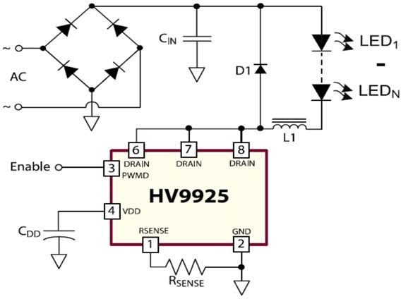
Have you tried this?

Mike.
 

I don't think I understand any of that. Your circuit appears to help. Now I just need a NOT gate I guess to drive the other voltage. Actually, I would need to have a short and a long pulse, as described. I'm not sure if this circuit does that. [edit] I can probably use that to have a big and small voltage, which might still be useful, but not the varying intervals.
 
I don't think I understand any of that.
neither do i - i forgot to exacten that
visually resembling
to . . . what i was hoping to find ► to better describe the vector forces involving to current or charge beam . . . .
i don't much get your intent anyway
(*related to plot you attempt to compile) a picture (of*) a schematic (of*) or the person names that have been investigated this subject before would help to focus the case better

  • as i get it your advantage here is the fact that you are not spoiled by conventional knowledge
  • the conventional knowledge may as well include and generally accepted misconceptions
    that are too convincing or natural to accept to doubt test or reject them
so if you have some idea of how your thing is to work then
  • write it down exactly as you have it
    • don't alter it as you write
    • don't attempt to clear it out or word it better while writing
  • then make a copy and describe the original text so that you will after 10y get the idea of every sentence or term used in
    • ones terminology and vocabulary (seem to be - i guess and in general) is a context related
    • ones terminology changes over time (especially what you also might mean by saying something)
      -- i have passed this mistake in past that writing up a novel theory won't ring any bells years later (when time to continue . . .)
      -- the crucial stuff is the bolded above - later you simply don't get there or wont see (know to look at) also it
it's something you much likely need to do for yourself
- to avoid getting lost in the subject
- to modify it on a run by getting attracted of it's sub areas (concentrating there and suddenly find yourself forgotten the original main plot)

no need posting such here
 
That's pretty interesting. I might go back to that.

My theories are just based on that simply passing an AC current back and forth in a wire creates the exact same amplitudes of an electromagnetic wave. And the AC signal frequencies match that of the waves. The waves are infinitely reducible to higher or lower wavelength signals decomposition by the assumption that every one of those relatively synchronized wave signals will have the waves of that wavelength returning to zero in between the crest and trough, or rather that they cancel out over that wavelength to give zero amplitude. It is like differentiation, where you count the difference between every two amplitude values to get a lambda*2 wave signal, with half as many values. The only thing that breaks this assumption is a blast wave or amplitude plateau. I think you already read the PDF's from my Twitter down a few months I think didn't you? It goes over this in more detail if you can read the cryptic writing and also covers much of the other ideas in the theory.

Also if you look at the gravitational waves animations from the plane of rotation and perpendicular to it, you can see this is the same basic idea. https://www.google.ca/search?q=gravitational+waves+animation

The energy that the electron loses is basically given off as light and momentum carrying mass. [Edit]

I'm already soldering the first test design and am going to test it using a spectrum analyser soon. [Edit]

In those gravitational wave animations, you can see the wave sizes and phases correspond to the objects going away and from a certain observer I thought. If you plotted the velocity component toward or away from an observer somewhere you would get a sine wave. What's interesting is that if you got closer to a comparably larger orbiting emitter you would notice it wasn't a perfect sine wave due to the changing direction of the velocity component toward you depending on the orbiters actual position at different phases. The gravitational waves would have different waves in those graphs if they were relative velocities because as one approached and the other receded they would be emitting opposite or different amplitude phases, not the exact same amplitude phase. [Edit] But the wave period and speed of wave propagation giving a distribution of a wave proportional to the separation of the orbiters suggests some relation of the wave phase to their relative velocity to some other observer.
 
Last edited:
... In those gravitational wave animations, you can see the wave sizes and phases correspond to the objects going away and from a certain observer I thought. If you plotted the velocity component toward or away from an observer somewhere you would get a sine wave. What's interesting is that if you got closer to a comparably larger orbiting emitter you would notice it wasn't a perfect sine wave due to the changing direction of the velocity component toward you depending on the orbiters actual position at different phases. The gravitational waves would have different waves in those graphs if they were relative velocities because as one approached and the other receded they would be emitting opposite or different amplitude phases, not the exact same amplitude phase. [Edit] But the wave period and speed of wave propagation giving a distribution of a wave proportional to the separation of the orbiters suggests some relation of the wave phase to their relative velocity to some other observer.
Google "Doppler Effect". Which, of course, has no effect on amplitude (that I know of), but that might be affected by the differentials in the objects' mass.
 
Last edited:
Status
Not open for further replies.

New Articles From Microcontroller Tips

Back
Top