Continue to Site

Welcome to our site!

Electro Tech is an online community (with over 170,000 members) who enjoy talking about and building electronic circuits, projects and gadgets. To participate you need to register. Registration is free. Click here to register now.

  • Welcome to our site! Electro Tech is an online community (with over 170,000 members) who enjoy talking about and building electronic circuits, projects and gadgets. To participate you need to register. Registration is free. Click here to register now.

Switch on 'click' from input of preamp permeating out - ideas sought!

Status
Not open for further replies.

HankMcSpank

New Member
Got a little problem, that's driving me potty!

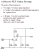
I've a guitar with it's output signal 'Y'ed off ....1 leg into an opamp preamplifier - the other leg has original guitar signal travels unabated onwards to a high gain guitar amp.

Here's the problem - when the preamplifier circuit is powered on/off (it's battery operated so can't be left on - and worse still needs to be switched on/off a lot), I get an annoying click out of the guitar amp.

Now I know what causes such clicks - sudden inrush current on power up (note: The circuit is required operate from a single 9V battery.). The transient in this case is the result of the opamp input pin biasing/ramping up to VCC/2 (virtual ground) too quickly - this small level surge finds it's way back out of the circuit input connection (in other words the transient travels in reverse trough the opamp input decoupling cap & back into the Y'ed off raw guitar signal travellling onwards to the high gain amp.

CLICK!

So, I then brought in a 7660 switched cap inverter .....to make the opamp supply bipolar thereby removing this sharp dc level at the input on power up - sure enough, click is virtually eliminated, but would you believe that on power off, I can hear the 7660 oscillator collapsing down out of my guitar amp! (like a peeeeuwwwww sound - only discerible upon switch off - & it's definitely the 7660!)


Any ideas on how to approach this, to rid myself of the click or other nasties as heard out of my hi gain guitar amp?
 
Last edited:
Have you tried putting a (larger) capacitor from the VCC/2 point to ground? That will slow the rise of the voltage to that point, if that is indeed the problem.
 
yes but the larger the cap, the greater the inrush of current into it upon power up ! (it didn't work)

It is definitely the area of problem - because holding vcc/2 on the right hand (circuit) side of the input cap up while powering on/off the rest of the supporting circuit has no audible click out of my guitar amp.
 
Last edited:
Why don't you post the schematic of your circuit so we can see where to add a capacitor to solve your problem? Please show the opamp part number.
 
This is the front end of it...

**broken link removed**

(the 2 x MCP1703s are actually a SOT23-3 5V regulator followedimmediately on by a SOT23-3 2.5V regulator- to give 1/2 VCC ......I couldn't be bothered to make my own Eagle library part, so just used those which are pin/package compatible!)

I'm not keen on slapping in large electrolytics as a solution, to give you some idea why, this is the size of board I've made (& I really don't want it to go any bigger)...

**broken link removed**

(& even that board above needs trimming down to size, as there's a lot of waste material around the edges).

I'm toying with going back to a charge pump inverter & going bipolar supply again - as I reckon it'll be very difficult to get rid of the clicks & keep the PCB real estate small - but I'm not sold on the 7660 at all. Maybe one with a much higher switching frequency (when experimenting with a charge pump inverter towards sorting this problem, I used a 7660 variant that switches at 45Khz...but there are much better ICs around that switch at eg 250Khz...and some have shutdown pins, which could be brought into play with a fet off the main 9V supply.)
 
Last edited:
The minimum supply voltage for a TL074 is 7V but maybe you found one that works from only 5V.
Your input capacitor C4 has a value that is way too high. It creates a -3db frequency at only 0.16hz. Use 10nF for -3db at 16Hz. The huge capacitor takes 5 seconds to charge and causes a loud BANG where a smaller capacitor makes just a little "click".

If you use a capacitor from R4 to ground instead of connecting R4 to half the supply voltage then the new capacitor can charge at the same rate as the input capacitor and eliminate the turn-on and turn-off BANG. Also then the half-supply can simply be two series resistors with a filter capacitor.
 
Last edited:
To eliminate the click, wire in a 10K to 100K resistor between Sig+ and Sig-Gnd.
 
Last edited:
To eliminate the click, wire in a 10K to 100K resistor between Sig+ and Sig-Gnd.
The output from the guitar is probably already grounded so adding a resistor will simply ruin its sound (the load on a guitar pickup must be at least 1M ohms).

It is the charging of C4 that causes the BANG.
 
The output from the guitar is probably already grounded so adding a resistor will simply ruin its sound (the load on a guitar pickup must be at least 1M ohms).

It is the charging of C4 that causes the BANG.

The last guitar pick up I played with was like a dynamic mic. It had an output impedance of ~10K. If the OP's pick up really has an impedance that high, then use a 1meg or 4.7meg resistor connected where I said.

Here is a previous thread that 'splains what is going on.
 
Last edited:
The OP has a circuit with a coupling capacitor feeding a 1M resistor to the bias voltage and the Jfet input of an opamp.
It is very similar to a guitar pickup preamp.
 

Attachments

  • guitar preamp.PNG
    guitar preamp.PNG
    15.4 KB · Views: 293
The input to the circuit is a 7.5K single coil pickup (nb: that 7.5K is a DC resistance...not the impedance)...not sure what purpose a resistor on the left hand side of the input cap would serve, because essentially the guitar pickup serves as a 7.5K 'bleed' resistor to ground there anyway.

It is the charging of C4 that causes the BANG.

Re C4 being too large - that value was picked specifically (for the circuit's intended application). Also, there's no bang, thud ...just a mild tick/click, which is only noticeable on hi gain amp settings - but I play on high gain settings a lot!

Like I say, I'm gonna explore a different higher frequency charge pump, which would eliminate any sudden VCC/2 'start up biasing on the rh side of C4.
 
Last edited:
The input to the circuit is a 7.5K single coil pickup (nb: that 7.5K is a DC resistance...not the impedance.
Audio circuits almost never match impedances. But old vacuum circuits needed to match the very high output of a vacuum tube to an output matching transformer. A guitar pickup is designed to have a 1M or higher load.

Re C4 being too large - that value was picked specifically (for the circuit's intended application).
I have never heard a guitar that produced 0.16Hz and lower. 1uF is 100 times too big.

Also, there's no bang, thud ...just a mild tick/click, which is only noticeable on hi gain amp settings
Maybe the very high value of C4 is good because it slows down its charging so there is no loud BANG.

Maxim made their audio switch that waits for a zero-crossing for a good reason: to eliminate a switching click.
Years ago I made an audio switch that ramped down the level of the first signal, switched then ramped up the level of the second signal and the switching click was eliminated.
 
I have never heard a guitar that produced 0.16Hz and lower.

Neither have I (not sure there'd be much of a market for one), but you've assumed the only significant role the input cap plays here is s a high pass filter (ie where the cap is sized for the lowest anticipated frequency) - it hasn't ......it's been spec'ed with phase response in mind.

1uF is 100 times too big.


No, it's not.
 
People are not sensitive to phase and guitars and other instruments all play slightly different frequencies so they are also not sensitive to phase.
Coupling caps are calculated for frequency response, not phase response.
 
People are not sensitive to phase and guitars and other instruments all play slightly different frequencies so they are also not sensitive to phase.
Coupling caps are calculated for frequency response, not phase response.

How do you know my circuit is designed for a 'person's ears' as the 'end of the signal chain'? (that'll be another assumption on your part!) You're making far too many bold assumptions/statements for a follow on circuit which you don't even know what the end use is! (there are no ears involved at the end of the follow on circuit)

Like I say, it was spec'ed with signal phase in mind & for that purpose it's the right value. ....but the next time I feel like a chunky portion of 'patronised on toast' coming on, I'll be sure to dine at your cafe.
 
You said that you have one guitar, a preamp and a high gain guitar amp. They are made to drive a speaker, not drive whatever you have.
Of course I assumed that they were listened to. That is what they are made for.
 
Maybe you could get rid of the regulator for Vcc/2 and replace it with a simple divider with a very large filter cap to slow the rise time way down.
 
Status
Not open for further replies.

Latest threads

Back
Top