Continue to Site

Welcome to our site!

Electro Tech is an online community (with over 170,000 members) who enjoy talking about and building electronic circuits, projects and gadgets. To participate you need to register. Registration is free. Click here to register now.

  • Welcome to our site! Electro Tech is an online community (with over 170,000 members) who enjoy talking about and building electronic circuits, projects and gadgets. To participate you need to register. Registration is free. Click here to register now.

Noisy analog switch

Status
Not open for further replies.

vielle568

Member
Hello Everybody,

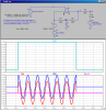
I've been building a circuit for an experimental musical instrument (the yellow object in the photo on the left) that takes an input from a magnetic coil type pick-up (Humbucker). The signal passes through a pre-amp/low pass filter and is then chopped by an analog switch that is controlled by the rhythm. The signal then passes through a final stage (a mixer) for amplification before output.


All is working correctly when hooked up with the instrument but the output signal is very noisy with clicks coming from the analog switch. The audio signal is biased at half the Vcc voltage as the op amps work from a single supply. There's a schematic attached showing the basic details of the circuit.

If someone can tell me how to eliminate the noise I'd be most grateful. Thank you for your suggestions.

vielle568
 

Attachments

  • numérisation0002..jpg
    numérisation0002..jpg
    1.1 MB · Views: 249
Last edited:
I would not want to say something wrong, as it is quite out of my confort zone, but wouldn't any sharp cut at a non zero crossing point generate plenty of harmonics for the back end to pick up from the pseudo square part (the sharp drop) of the signal.
 
I think you need to have a fixed impedance on your switch output pin 8, like a resistor to ground.
 
I'm thinking that the clicks are coming from the capacitive feed thru from the squarewave being used to control the analog switch. Try a low-pass filter to slow the turn-on/turn-ff of the switch.

Try eliminating the 100nF capacitor on the output side of the switch.

With the switch off, check to see what the DC level is on the input and output side of the switch. Minimize that offset, if any.
 
You could be right Superfrog, however from a previous forum suggestion I was advised to bias the input signal because I was using single supply op amps and the ac signal wouldn't be able to swing below ground. I was also told that the bias should eliminate the clicks coming from the analog switch but it doesn't seem to be the case.

If I put the analog switch at a different position in the circuit (at the start; at the end) would this make any difference?
 
Hmmm. I dont think the clicks are coming from the digital feedthrough of the drive signal. If anything they will be coming from the stray capacitance across the internal FETs inside the switch itself. Slowing down the digital waveform will not any effect on this... as well as the fact that the digital drive (however slow) goes intoa logic gate, so will be squared up anyhow

I think your best bet is to move the switch to the output of the op amp - at least then any charge injection will be injected into a low impedance node (the op amp output). Not sure if this will work, but at least try it.
 
Hi Mikebits and MikeMl,

The DC level on the input side (pin 1) of the analog switch is at 4.5v when there's no signal and around 5.5v when a signal passes. On the output side (pin 8) the DC level is at 8.93v when these's no signal and it drops to about 5.6v when the switch opens and the signal passes.

There's quite a considerable offset but how do I reduce this difference?
 
Maxim make an analog switch that waits for a zero-crossing then switches without a click. Your analog switch switches maybe when the audio signal voltage is higher or lower than the voltage at the coupling capacitor it feeds. Then a click is heard.

A suggestion was made to add a resistor to ground at the output of the switch that will make a very big BANG when it switches.
 
Now that you posted the voltages, I am convinced getting rid of the 100nF coupling cap on the output of the switch will help!
 
Last edited:
hi,
Its as 'agu' says, you need to detect the zero crossing point of the audio signal and operate the analog switch at that zero point.

If you consider that the analog signal could be at maximum when the switch operates you will get a 'click'

EDIT:

AAesp03..gifAAesp02..gifAAesp04..gif
 
Last edited:
Here is a network that eliminates a click if it is due to a difference in offset between the input and output side of the switch. Per AG and Eric, I purposely set the switching signal to coincide with when the the input signal is at maximum.
 

Attachments

  • D4.png
    D4.png
    36.6 KB · Views: 194
I ran into this using a CD4066 in a 4-place aircraft intercom. I was VOXing 4 individual channels, through a capacitor, into an LM386. Just like the OPs second stage. Because the coupling cap has no discharge path, when the analog switch opens, there is a charge left on the cap. The next time the switch is closed, unless the input voltage is exactly the same as when it opened, it will rapidly charge or discharge the cap and cause a pop. I solved my problem by biasing the input side of the cap with a 100k/100k voltage divider, placing both ends at the 1/2Vcc reference voltage.

Ken
 
Mike,
The LTS asc file, save you creating it.

I would have thought the OP could use say, an LM393 as a ZCD for the audio signal and sync the gate enable to the zero cross over.
 

Attachments

  • Switch1..asc
    3.9 KB · Views: 141
Maxim make an analog switch that waits for a zero-crossing then switches without a click. Your analog switch switches maybe when the audio signal voltage is higher or lower than the voltage at the coupling capacitor it feeds. Then a click is heard.

A suggestion was made to add a resistor to ground at the output of the switch that will make a very big BANG when it switches.

Not questioning that you are correct or not, but would you care to explain why you think a fixed impedance would cause a bang? According to the maxim data sheet, the spec test were conducted with a fixed output Z.

**broken link removed**

Thanks in advance for clarification.
 
Last edited:
hi Mike,
I 'think' agu means an acoustic bang in the sound output rather than an explosive bang.;)
 
Last edited:
hi Mike,
I 'think' agu means an acoustic bang in the sound output rather than an explosive bang.;)

Yeah, I assumed that but why? I am not sure why an unterminated node would be better than a terminated one.
 
Yeah, I assumed that but why? I am not sure why an unterminated node would be better than a terminated one.

hi,
A couple of runs with LTS to show, with 10K and without 10K on the switch output.
Its the 100nF which is being charged/discharged that causes the output to 'bang'.
The image showing the exponential decay is the 10K one.

AAesp07..gifAAesp08..gif
 
Your simulation shows the terminated one at 4.5V max with slower edges which makes sense, and the unterminated at a higher voltage with quicker edges, if anything I would think the latter to produce the pop, but I will not belabor the issue as I am not really sure. Thanks for doing the sim, I appreciate the time you put in to help explain it. :)
 
Your simulation shows the terminated one at 4.5V max with slower edges which makes sense, and the unterminated at a higher voltage with quicker edges, if anything I would think the latter to produce the pop, but I will not belabor the issue as I am not really sure. Thanks for doing the sim, I appreciate the time you put in to help explain it. :)

hi Mike,
The 'problem' is the split power supply, at rest the OPA outputs are at +4.5V.
So connecting the 100nF effectively to 0V via the 10K discharges the 100nF which recharges when the switch is closed.

Hope you you are well.:)
 
Okay I am with ya:) From what I got from the data sheet though was that the FET in the switch holds a charge and on closure a high impedance may cause a pop. Never been great with analog, I suppose that is why I went into the medical field :)
Thanks for explaining :) Hope your well also.
 
Last edited:
Status
Not open for further replies.

Latest threads

Back
Top