2camjohn
Member
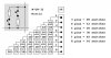
I am trying to save on inputs by multiplexing three switches to use two inputs..
I get the idea in theory, which is that 2 inputs can have 4 states 00 01 10 and 11.
but I cant figure out how to wire up my switches. Simply wiring one switch to both inputs to make a 11 doesnt work for obvious reasons...
The switches are simple push to make buttons using weak pullup resistors (external, not the ones built in to the PIC).
I have googled for switch multiplexing, but cant find anything useful.
If anyone can offer any help on how to wire this up, or point me in the right direction I would be grateful.
Thanks
John
")
