Electro Tech is an online community (with over 170,000 members) who enjoy talking about and building electronic circuits, projects and gadgets. To participate you need to register. Registration is free. Click here to register now.
Welcome to our site! Electro Tech is an online community (with over 170,000 members) who enjoy talking about and building electronic circuits, projects and gadgets. To participate you need to register. Registration is free. Click here to register now.
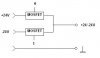
I need to build switch for switching positive and negative voltage, like you can see on the picture. I thing that this possible to do by MOSFET's but not shure how exactly. Can I use P and N MOSFET's?
I need to build switch for switching positive and negative voltage, like you can see on the picture. I thing that this possible to do by MOSFET's but not shure how exactly. Can I use P and N MOSFET's?
You give almost no details about your requirements, but the scheme you suggested is fraught with danger! - I can see both FET's being switched on together and a big BANG!!.
Obviously it depends on what you are trying to do (and why!), but a relay with single pole changeover contacts would do it simply, reliably, and safely.
OK! I have to control wall clock, what count each second from impulse (for each second i must to invert polarity of 24V). So each second polarity of 24V must be changed.
I do not want to use relays because they make a noise and have limited swithing cycle. I start to control this MOSFET's by MCU. I have about 30 clock s in parallel, so MOSFET's must switch some amps (not more than 5A).
Can somebody suggest, how exactly I can use MOSFET's for this?
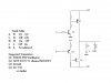
it is easier to do with 2 transistor push-pull circuits: http://www.ecircuitcenter.com/Circuits/pushpull/pushpull.htm The first circuits is ok, just put one driver transistor (48 Volt powered) witch on its turn is driven by your clock circuits.
The first circuit (PUSHPULL.CIR ) in the web site would suffice. But you must switch VS1 between the positive and negative rails ie. between VPOS and VNEG.
Alternatively, you could use Enhancement Mode MOSFETs in the same configuration.
What is the circuit driven by? Is it, for example, from a CMOS circuit that has a +5 Volt supply?
At first I thinked to use H-Bridge and common voltage (VCC/GND). But I want to erduce components and price of device. So I decided to find solution with only 2 MOSFET's and positive/negative/GND voltage.
I'm not good in electronics (especialy with transistors and MOSFET's). I tried some schematics with transistors to switch positive and negative voltages to 1 wire, but in schematic simulator I have no sucsess (when connect two transistors together). I plan to drive transostors/MOSFET's with CMOS signal from MCU (5v). To write program for MCU not problem for me, but schematic... :roll:
Can I use 2 MOSFET's with logic signals (like IRL)? Is somewhere in internet some schematic? H-Bridge schematic I have, but schematic with 2 transostors (PUSHPULL.CIR) I not understand, of cource I can convert it to MOSFET's... Can somebody help :?:
If you have 2 X 24 Volt source you can use a 2 transistor or 2 Mosfet solution. If you have only ONE 24 Volt supply you must use the bridge,
the bridge is designed to invert.
At first I thinked to use H-Bridge and common voltage (VCC/GND). But I want to erduce components and price of device. So I decided to find solution with only 2 MOSFET's and positive/negative/GND voltage.
I'm not good in electronics (especialy with transistors and MOSFET's). I tried some schematics with transistors to switch positive and negative voltages to 1 wire, but in schematic simulator I have no sucsess (when connect two transistors together). I plan to drive transostors/MOSFET's with CMOS signal from MCU (5v). To write program for MCU not problem for me, but schematic... :roll:
Can I use 2 MOSFET's with logic signals (like IRL)? Is somewhere in internet some schematic? H-Bridge schematic I have, but schematic with 2 transostors (PUSHPULL.CIR) I not understand, of cource I can convert it to MOSFET's... Can somebody help :?:
Thanks to all for so clear advises! I start to experiment with this solutions.
BTW: I found on our local electronics distributor H-bridge chip (L298N).
It's consist of two full-bridge drivers, each for 2Amps. I can use them in parallel, so I get 4A from this bridge, and it's costs only about 4 Euro.
I would not put them in parallel. I would drive half the clocks from one and the other half from the other.
Some multimeters can measure inductance. You can measure the resistance with a multimeter. If you can't borrow a MM that measures inductance, it can be determined if you have an oscilloscope.
If I use Davids solution, and cut off logic components, and do they work in MCU (to generate pulses, what not overlap each other), is it's correct?
Pavel.
I assume it is some type of micro processor. If so, then you should be able to programme it to prevent overlaps. But there are more issues to be considered.
2. I can't use the half of clocks because they allready all connected to one line.
3. With timings I haven'tt any problems I think, because, between switching +/- I have about 0.4 sec. MCU must give this secuence: 0.8 sec - (one direction), 0.4 sec - Hi-Z, 0.8 sec - (reverse direction), 0.4 sec - Hi-Z and so on...
4. I have resistance on coil about 3.2K (on clock contacts). It's interesting, that when I manualy turn a clock, then resistance changed from 3.2K to 6K, then suddenly goes to 100Ohms, then back to 2.5K... I don't know how this clock works... :?:
This site uses cookies to help personalise content, tailor your experience and to keep you logged in if you register.
By continuing to use this site, you are consenting to our use of cookies.