Continue to Site

Welcome to our site!

Electro Tech is an online community (with over 170,000 members) who enjoy talking about and building electronic circuits, projects and gadgets. To participate you need to register. Registration is free. Click here to register now.

  • Welcome to our site! Electro Tech is an online community (with over 170,000 members) who enjoy talking about and building electronic circuits, projects and gadgets. To participate you need to register. Registration is free. Click here to register now.

Super HeadBanger (??) Review request

Status
Not open for further replies.
Thank you audioguru :D
I look foward to meet you and taste some Brazilian barbecue 8)

By the way, the board is up and ready to kick, now i'm finishing out the aluminium box that I've choose to be the last home of my Super Headbanger. :p
 

Attachments

  • bb.jpg
    bb.jpg
    26.7 KB · Views: 343
  • bc_673.jpg
    bc_673.jpg
    43.2 KB · Views: 361
Hi Wellington,
I'm glad to see that you are using proper shielded cable to your volume controls!
That 6VA transformer looks huge! Don't drop it on your feet.
 
Hi audioguru!

Audioguru, i've used that shielded cable on the **broken link removed** too, they are the same type and from the same reel :lol:

By the way, let me say one thing.

DAMN!!!!!!!!

I've changed the value of capacitors C11/C16 to 15n like you said, DAMN!!!!!!!!

The circuit BASS BOOST is stronger than my SONY walkman/discman BASS BOOST (aka MEGA BASS). Some friends of mine are using this amp in a LAN HOUSE to play Counter Strike with it, and they are amazed about the circuit performance.

I did a new test, connected the circuit to my SBLive 5.1 front output, winamp v5.04 + **broken link removed**, configure Enhancer with Deep Bass Boost preset, and put it the Usher ft Lil' Jon & Ludacris - Yeah to kick.

DAMN!!!!!!!! (x3)

You don't imagine the BASS power that this circuit can output, it has transformed it self in to a BASS BEAST!
Is so smooth and powerful that i still can't belive it!
Using the same settings with my Live drive II headphone output it can't reproduce the same power as the circuit can.

Sh*t, i've not designed the circuit to be used like this (computer audio card output), but damn, it's good man, very good!!!!!
 
I think the solid bass is because your large output capacitors continue to pass frequencies 'way down to 5.3Hz.
I listen to Usher and like the deep punch and the hushed tiny bells.
 
Thanks audioguru!

Now that the circuit is done and finished, here is the plot that you have asked:

(Tone 1 = f1) = 1001 (Hz) = 14,5 dB rms

Freq.(Hz) Harmonic Value (dB rms)
2003 (2*f1) -55,0
3047 (3*f1) -66,7
4005 (4*f1) -71,7
5125 (5*f1) -83,3
6105 (6*f1) -69,7
7074 (7*f1) -85,4
8118 (8*f1) -83,0
9076 (9*f1) -81,1
10185 (10*f1) -83,7

THD = 0,0767%
1.2V RMS
40 Ohms load
 

Attachments

  • xamp-thd.png
    xamp-thd.png
    4.6 KB · Views: 393
Hi Wellington,
Most numbers seem to be shifted upward by 14.5dB. The reference, Tone1 should be at 0dB and all the harmonics measured downwards from there. For example, Tone2 should read -69.5dB, which is about 0.03%. The total distortion of only 0.0767% should remain the same.

Your graph looks good, but now you are cheating and not showing how good your circuit is. Your new graph stops at -50dB at its bottom, which is about 0.3% distortion. If you change the graph's range so that it stops at -60dB, like it did before, then it will show that your circuit's distortion is less than 0.1%, which is true. If you extend the range to -70dB (0.03%), then it will barely show a tiny blip for Tone2, which is also true.
 
Hi audioguru!

Sorry my fault, i was not trying to cheat no one, the recording levels was all mess up (14,5 dB is too much), now with the recording level with 50% (as the program manual ask to do) this is what i've got.

(Tone 1 = f1) = 1001 (Hz) = 7,6 dB rms

Freq.(Hz) Harmonic Value (dB rms)
2003 (2*f1) -56,4
3015 (3*f1) -68,5
4005 (4*f1) -74,6
5082 (5*f1) -85,0
6105 (6*f1) -72,8
7041 (7*f1) -84,9
8150 (8*f1) -82,9
9162 (9*f1) -84,7
10088 (10*f1) -82,6

THD = 0,0664%

Also, here are the same plot at 0-56, 0-60 and 0-130 range.
 

Attachments

  • thd3.png
    thd3.png
    6.4 KB · Views: 358
  • thd2.png
    thd2.png
    4.8 KB · Views: 350
  • thd4.png
    thd4.png
    4.8 KB · Views: 346
Hi Wellington,
Tone1 is lower, but is still not at 0dB. So turn the recording level down even more.
Also make certain that the output of your circuit is still at 1.2VRMS and that it is not clipping.

Doesn't your analyser's graph have a 0dB to -70dB range?
 
Hi audioguru,

Sorry audioguru, i'm new with this stuff and i'm dying to learn more :D
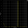
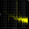
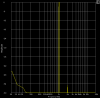
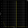
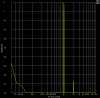
This is the closest that i could get because the scpro oscilates before returning the final THD. (or is my fault setting it up)

Output level is stable at 1.0V AC(before clipping)

(Tone 1 = f1) = 1001 (Hz) = 0,3 dB rms

Freq.(Hz) Harmonic Value (dB rms)
2003 (2*f1) -62,5
3101 (3*f1) -80,3
4005 (4*f1) -74,4
5039 (5*f1) -94,1
6105 (6*f1) -76,5
7149 (7*f1) -93,7
8096 (8*f1) -92,1
9119 (9*f1) -90,4
10153 (10*f1) -91,7

THD = 0,0767%

Here is some more information that i could measure from circuit at 1.0V output, 40 ohms load.

Signal from source: R 1.505V AC/ L 1.515V AC (Xbox audio output)
L/R difference: 1% (From Sample Champion)
Input level after R4: 0.125V AC
Input Level after R9: 0.123V AC
Output level before R7/R8: 1.001V AC- 1.002V AC
Output level after R7/R8: 1.000V AC- 1.001V AC
Output level before R12/R13: 1.021V AC - 1.022V AC
Output level after R12/R13: 1.020V AC - 1.021V AC
Circuit Power Consumption: 25mA
Voltage Output (with negative at D1 cathode, positive at 7805 VOUT): 5.68V DC (stable)
Voltage Output before D1 (with negative at D1 anode, positive at 7805 VOUT): 5.03V DC (stable)
Voltage Output before R1(positive at 7805 VIN): 11.90V DC - 12.58V DC (variable charge/discharge)
Voltage Output after R1(positive at 7805 VIN): 10.19V DC - 10.23V DC (variable charge/discharge)
Voltage Output before R1(positive at 7805 VOUT): 7.35V DC- 8.00V DC (variable charge/discharge)
Voltage Output after R1(positive at 7805 VOUT): 5.68V DC (stable)

Now that i've decided to do all this measurements, it would be nice if some one could simulate or test with a osciloscope to see the influence of R1 with the ripple voltage, because without R1 i can hear the hum at the output. Also D1 at the regulator, i know that it will boost the output voltage by 0.7V but removing this diode i also can hear a small hum noise at the output.

Changing for example the 7805 (5.03V DC) to 7806 (6.02V DC) (so i could remove that voltage boost diode) it will not get any better, 7809 (9.03V DC) is worse, the hum noise increases. So the R1/D1 was added (by trial and error) in the attempt of remove the anoying hum at the headphones (by the way, this noise is much worse with the original headbanger), that worked fine, if there are some noise at the output i can't hear it in a very quiet ambient with this configuration and the volume shut.

Give it to me strait audioguru, there is something wrong with the circuit? :shock:
 

Attachments

  • thd-5.png
    thd-5.png
    4.8 KB · Views: 325
Hi Wellington,
You have the analyser close to 0dB now. I don't know why you can't get the Tone1 reference at exactly 0dB, and I don't know why your SCpro oscillates when you try.

Your measurements show that there is no voltage drop across R7/R8 and R12/R13 so you must have measured without a load. That will also affect current consumption, but music is never "full output always" anyway, so the average current consumption will not be much more.

Your voltage measurement "before R1" is much lower than I expected because R1 does not allow C2 to charge to the peak voltage of the sine-wave, and therfore the voltage "before R1" has a lot of ripple on it and measures low. That is fine with your 12VAC transformer.

Your addition of R1 and D1 to eliminate hum is probably because the rectifiers radiate a "buzz" sound when they switch. Your nearby circuitry picks-up this radiation, but with R1 and D1 then the ground voltage also picks up this radiation equally to the rest of the circuit and the buzz cancels. Also, R1 limits the charging current of C2 which substantially reduces the peak switching current through the rectifiers. Frequenly audio circuits have capacitors of 10nF to 100nF wired across each rectifier diode to eliminate this radiation.

Your circuit is very good and has nothing wrong with it.
You did a fine job.
 
Hi there!!!

So, after a few days after the final design of this project, i had a lot of feedback from people that had builded this amp with 100% satisfaction. Some of my friends are using this amp in lan houses, internet cafe and so on.

And because of that as I told audioguru, i've changed the circuit again because of this feedbacks and the different headphone sets that are out there, some noticed that the BASS was not strong the way i told it was, and others the volume was too low with high impendance headphones etc, and i waited a few days so i did not have to change the circuit to many times.

So the input resistor was reduced a bit and removed the output resistors, the overall THD did not change much (0.1%~0.2%), some headphones that had a frequency response from a range of 20Hz~20Khz have a dry bass in the other hand headphones with frequency response of 10Hz~20KHz have the strong dep bass that i've told before.

Many headphones was tested, including SONY, Panasonic, Kenwood etc, thouse brands are the most used here in Brazil.

Also, thouse that have builded the circuit noticed that they can't get rid of the resistor and the diode at the circuit power supply, because of the overall noise that increases.

The circuit performance still very good, i've tested i few other headphone amplifiers circuits, but none of then has the BASS response that i like, most of then sound like a tweeter to me or the project is so complex and had so much components in it that i really did not want to try at all. And if I really want a perfect, super low THD, kicking BASS headphone amplifier it would be more simple to buy a system instead of building one.

Well, this is it, the circuit is ready and is much more stable than the original one, and i hope to finnish the portable version soon.

Thank you all the people that builded this circuit and audioguru that helped me out many times.

The final circuit home page is located **broken link removed**.
 
Status
Not open for further replies.

Latest threads

New Articles From Microcontroller Tips

Back
Top