Continue to Site

Welcome to our site!

Electro Tech is an online community (with over 170,000 members) who enjoy talking about and building electronic circuits, projects and gadgets. To participate you need to register. Registration is free. Click here to register now.

  • Welcome to our site! Electro Tech is an online community (with over 170,000 members) who enjoy talking about and building electronic circuits, projects and gadgets. To participate you need to register. Registration is free. Click here to register now.

Super HeadBanger (??) Review request

Status
Not open for further replies.
Hello Guys! :D

I have build 20 variations of the same Headbanger circuit. The main problem was the "hummm", noise and the BASS that was to weak.

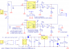
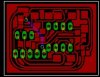
So i came up with this circuit(based on headbanger):

No "humm" or "shhhh" (Hisss)
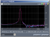
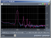
Better Bass response
Better volume control
Low distortion in max volume
No oscilation
No ground problem

Please note that i am not a electronic engineer nor i do have equipament to make technical documentation about this circuit, the only thing I had was my ears. :lol:
This device was tested with xbox XBMC and SONY **broken link removed** headphones.

With songs from nirvana, guns, eminem and so many, the bass response gives a big punch (compared with the original), very clean and smoth. If you do a teste with thouse "BASS test songs" like DJ Magic Mike Bass Test, you can feel the BASS pressure in your head, powerfull and smoth or if your headphone can keep up with the song "Deep ass bass song", for the first time i understood what the "Deep bass" mean, to strong!

I felt that i was throw up....no joke.

So, i will be very glad if some one could comment or give any suggestions about this circuit.

Thanks

**** 08/27/2004 Schematic updated
 

Attachments

  • x-amp_181.png
    x-amp_181.png
    18.9 KB · Views: 991
how much current does this thing consume? because many people are only going to use a headphone amp when out and about, otherwise they'd use a normal hi-fi.

Don't get me wrong, I'm not trying to put your design down.

Tim
 
No problem grrr_arrghh.
I dont know how much this consume (now) because I am tired of making changes in this circuit, let me take a break and i will supply that information to you.

I also have a hifi and a complete Home Theater set with **broken link removed** projector etc to watch DVD and hear music, but i use this in my room since there is no sound isolator, i've build this circuit to play xbox games and hear my mp3 in it without the need to power on my 900W computer just for that, i have a good 5.1 amp in this computer and like to listen mp3 from it, make the windows shake but my neighbors don't enjoy that as I do, so...

To make it portable you can add a **broken link removed** and make a Step-down Switching Regulator as many diskman/walkman/portable mini-disc uses to help boost batery life a bit.

Here a example of a **broken link removed** circuit with board and here a few more examples and explanations about **broken link removed**.
This circuit solves many problems from the original headbanger, so i still want to hear some comments about it.

Thanks :wink:
 
have you actually constructed a finished unit from that schematic? I am just wondering as I just designed a really small PCB for it, and I am currently thinking about how to isolate the ground loops (input/output)

I'm doing each of the two channels on its own board (ie- two mono amplifiers) with a 4-pin input connector: VS, signal, Input ground, and output ground. then I'll have one very simple main board that will have little more than connections to the power supply and audio input.

If anyone has any tips or pointers on board design for audio circuits to reduce feedback, etc, then please let me know. I attached my mono amp board layout. as you can see, everything is crammed into as small a space as possible, and all empty space is filled with a copper pour. the pour is not grounded though, so i'm not sure it will help, but it does help the etch resist transfer more easily to have less empty space.
 

Attachments

  • board_layout.jpg
    board_layout.jpg
    16 KB · Views: 1,178
Hey evandude thanks!

My board is not small as yours but, yes i do have a **broken link removed**, is a prototype not a final version, moust components are under the board.

The photo of the first circuit is the original headbanger version, the second photo is the final prototype based on the improved version of headbanger (my schematic). As you can see i did not yet add a metal shield because is a prototype (yet based on my schematic), the final version will have that shield and will be small as your board that i will build with SMD components and the transformer/power circuit will be build outside from the main board.

To shield the board i will add 4 ceramic capacitors like specified in the schematic, TOP, BOTTON, LEFT and RIGHT near out side the board (all centered) from RGND to the metal shield, yet to prevent oscilation of the circuit and prevent noise.

I did not have any problem with the GND, note that all external conectios are made with shielded cabes, I just put all together BUT check the power supply, i had many problems with noise ripple (humm, hisss, buzzz) that was loud when used with any AC adapters. I know that the circuit looks wrong (R1/D1) but without the components as specified in the power supply schamatic it will feed the circuit with noise. Some people told me that i dont need the 100R in the GND or the D1, but if removed the humm will increase.

I did a few tests with 9v battery and SONY NP-FM50 InfoLithium type M battery, the circuit still very stable, no oscilation and with the same sound quality, but before I do any more tests with battery, the main circuit is finished and i will try not change it, i will add a **broken link removed** like many portable devices has to boost battery performance.

I tell you this evandude i have past the last two months in this circuit trying to get the best result possible (audioguru knows and help me alot :D ), using this circuit with for example a SONY Discman with "Mega Bass" turned on you will get a impressive, high quality sound yet with good punching BASS.

If you build this circuit let me know :wink:
 
I will. I designed that board in such a way that if i solder long pins down through 4 of the 5 holes in the 5-pin header, and then run wires down for the remaining hole on each board, I can simply stack two of these boards on top of each other, with only the thickness of the IC between them. then, I plan to design the third (main) board to about the same size, so the whole thing will probably look something like a cube :) 1.25" by 0.9" by maybe 3/4" thick.

I can post some finalized board designs in the future, when I actually prototype them, if anyone is interested. I might try etching one soon (this weekend maybe?) and then maybe i'll get a chance to try it out.
 
Hi Wellington,
Are the plots good? No way! The output should look almost like the input.
They show an awful lot of harmonic distortion, more than a few percent, which is much more than a basic LM386 and very much more than the original Headbanger circuit. I hope that those plots were measured with a load, because if they weren't, then the distortion will be even higher when loaded. View the output's sinewave to ensure that the amp isn't clipping.

Your choice of a low value for C7 and C13 eliminates many benefits of the original Headbanger circuit, such as lower distortion at low frequencies and extended low frequency response, but it does give a little bass-boost.

The LM386 is not designed to have a capacitor to ground on its pin 8, which is probably where your excessive distortion is originating, especially the unusual even harmonics. Instead, using capacitors with a much higher value for C9 and C15 would probably reduce the ON/OFF "pop" (but cause a turn-on delay).

The input capacitors C5 and C11 are not necessary (and their values are much too high anyway) because the LM386 is designed to have its inputs biased at ground, which would come directly from your volume controls.

Sorry Wellington, but nice try. There are many good headphones' amp chips out there, but most are SMT only. Try experimenting with an MC34119, which is a small bridged amp not requiring an output capacitor. With a gain of only one, like your circuit, its distortion should be vey low. Its datasheet is here:
**broken link removed**
 
Hi Audioguru!

I am sorry for that, I just trying to do my best :cry:

Sorry, forgot to put a dummy load, now i am using a 40 Ohms load (same as my headphones impedance) in both channels, I think now the mesuraments will be more accurate.

C7/C13 came out of the LM386 datasheet, in the original headbanger i did not felt the bass-boost as promissed, it was more like a headphone amp with a very little bass improvement but like you said it kills the benefits of the original verion of headbanger.

I have changed the C9/C15 to something like 100uF, it wont get any better, it just delay the "pop".

I am not a bass freak, but i think it's nice to feel de bass pressure and again like you said there will be some pay off in High Fidelity, C5/C11 was added to some extra bass.

Now that the dummy load are in place i've done a few more tests (1Khz sine wave) using the Sample Champion from Pure Bits so i could check the THD and see not only graphics but numbers.

This is the result of circuit based on my schematic (no changes):

With C8/C14
(Tone 1 = f1) = 1001 (Hz) = 5,6 dB rms

Freq.(Hz) Harmonic Value (dB rms)
2003 (2*f1) -27,1
3004 (3*f1) -61,1
4005 (4*f1) -36,8
5006 (5*f1) -58,4
6105 (6*f1) -73,7
7031 (7*f1) -85,3
8086 (8*f1) -88,3
9162 (9*f1) -93,5
10099 (10*f1) -84,5

THD = 4,4410%

Now the same test Without C8/C14:

Without C8/C14
(Tone 1 = f1) = 1001 (Hz) = 6,2 dB rms

Freq.(Hz) Harmonic Value (dB rms)
2003 (2*f1) -46,5
3004 (3*f1) -63,6
4005 (4*f1) -40,8
5006 (5*f1) -49,4
6105 (6*f1) -71,5
7031 (7*f1) -61,3
8043 (8*f1) -87,3
9076 (9*f1) -87,8
10088 (10*f1) -83,2

THD = 0,5341%

THANK YOU AUDIOGURU :D

There is a japanese that did a few more test with the headbanger and like many others, he find out that the original headbanger was not that good as the author say it was. If some one understand japanese you can see all the technical tests he did **broken link removed**.

And like the test he did, you can get better results if R4/R7 (my schematic) has 20K resistors, so i did change R4/R7 to be 20K and this is the final results:

(Tone 1 = f1) = 1001 (Hz) = 6,2 dB rms

Freq.(Hz) Harmonic Value (dB rms)
2003 (2*f1) -56,9
3058 (3*f1) -76,2
4005 (4*f1) -68,3
5103 (5*f1) -89,1
6105 (6*f1) -75,1
7095 (7*f1) -87,0
8107 (8*f1) -89,3
9055 (9*f1) -85,2
10099 (10*f1) -84,2

THD = 0,0935%

Now i think this is a better result :D
I dont want to flood the forum with plots, so this is the final plot, I think it could be better but in my tests the sound get more flat killing the bass response, and for a cheap head amp i dont think it could get any better with the bass that i like (personal taste).

Once again thank you audioguru for your help and i will try the MC34119.
 

Attachments

  • changed.png
    changed.png
    4.8 KB · Views: 1,073
Hi Wellington,
I'm glad that you got the distortion down to where it belongs, an improvement of more than 47 times lower! Removing your capacitors C8 and C14 to ground at the LM386s' pin 8 made a big difference. Increasing the value of your feedback resistors R4 and R7 also helped, by eliminating the "snapback" distortion at low supply voltage (like you are using) as mentioned by the author of The Headbanger, and eliminating the instability (severe ringing with sharp transients like square waves) as reported by the Japanese gentleman.
Now that your feedback resistor values are increased, your bass-boost is reduced from your original 8dB at 100Hz (National's bass rolls-off because their output capacitor is only 220uF, and is driving 8 ohms), to only about 4dB at 50Hz. You can return the boost frequency to 100Hz by reducing the value of capacitors C7 and C13 to 0.015uF, then the bass will be almost what you like.
It is too bad that you can't get rid on the turn-on "pop", but that's what happens when the output capacitor charges quickly through your headphones.
Remove C5 and C11 and replace them with jumper wire since they don't do anything. Try shorting them to see (hear?).
 
congrats wellington, and thanks audioguru.

You should post up an updated schematic after you try audioguru's latest tips.

I've got all my SMD board designs done but I'm waiting to etch them until you have decided on a more final design :) looks like things are going well, keep up the good work.
 
Hi Audioguru!

Latter i will try C7/C13, the store is too far from here.. :D
Also removed C5/C11, sound and THD looks the same, so they are out now.

Thank you very much for the help that you gave me (more than once) on this project!
:D

Project done, enjoy it!

Thank you audiuoguru, thank you everyone.
 
evandude said:
congrats wellington, and thanks audioguru.

You should post up an updated schematic after you try audioguru's latest tips.

I've got all my SMD board designs done but I'm waiting to etch them until you have decided on a more final design :) looks like things are going well, keep up the good work.

Thanks evandude!!
I have a meeting now, i will update the schamatic soon as i get home. I think the final design is good the way it is, the sound is now better, low noise.

Have to go, i will update the schamatic soon.
bye!
 
Hi Wellington,
Your final circuit is almost identical to National Semi's, isn't it?
But their datasheet for the LM386 doesn't mention the "snapback" distortion at low supply voltages that was discovered by the author of The Headbanger.
The MC34119 is bridged, therefore stereo headphones will need to be re-wired to be 4-wire.

Hey Evandude,
If you want to make a really small, but good quality headphones amp, then MAXIM have some stereo headphones amp ICs (surface-mount only) with a built-in charge-pump circuit that develops a negative supply, therefore input and output capacitors aren't needed and the effective supply voltage is doubled. Some of them operate from a single, small battery cell.
National Semi also make some surface-mount stereo headphones amp ICs. At least one has 3 amps, with the 3rd being used to provide a regulated (therefore no big filter cap) bias-voltage "ground" for the headphones, so that output capacitors aren't needed. Since it needs at least 2 battery cells, the 3rd amp isn't needed if you "ground" the middle connection of both cells, and besides not needing output capacitors, it also won't need input capacitors this way.
All these new ICs have built-in "click and pop" suppression circuitry.
 
Status
Not open for further replies.

Latest threads

New Articles From Microcontroller Tips

Back
Top