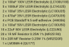
Sometimes I think there's a little bubble surrounding my workbench in which the normal laws of physics cease to apply! I built the lm386 circuit, attached diagram with exact components that I used. The thing is not that the circuit doesn't work , it does and surprisingly well. Its that the lm386 is oscillating at nearly 150Khz! I checked my scope against a known reference just to be sure that it was measuring correctly and it was. The circuit in the article was supposed to operate around 25Khz, which sounds about right for a 10k timing resistor and 2.2n, I tried 1n and 1n8, it did slow down marginally going from 1n to 1n8, this is a bit of a mystery to me, though I managed to get ~83% efficiency with 10 volts in and a 240 ohm load yielding just over 17 volts at the output.
I forgot to include another 1u ceramic in parallel with the electrolytic output capacitor in the attached diagram, I did use one in the actual circuit.