Continue to Site

Welcome to our site!

Electro Tech is an online community (with over 170,000 members) who enjoy talking about and building electronic circuits, projects and gadgets. To participate you need to register. Registration is free. Click here to register now.

  • Welcome to our site! Electro Tech is an online community (with over 170,000 members) who enjoy talking about and building electronic circuits, projects and gadgets. To participate you need to register. Registration is free. Click here to register now.

Strange behaviour of mc34063 step up circuit

Status
Not open for further replies.

Gasboss775

Member
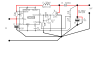
I built the attached step up circuit using an mc34063 and an external IRL2910 N Ch MOSFET. With the component values shown the mc34063 operated at nearly 200 KHz and the output was around 10 volts, with a 100ohm load instead of the design figure of 15 Volts.
This operating frequency is way above that stated in the data sheet. Is there any reason why it would do this with the external switch rather than the in built one.

Note it was an ONsemiconductor mc34063.
 

Attachments

  • mc34063 stepup circuit_09_11_2005.png
    mc34063 stepup circuit_09_11_2005.png
    58.8 KB · Views: 19,595
The reference voltage is 1.25V, so R3 and R4 will give an output voltage of about 11.7V, not 15V.

Don't know why its operating at 200kHz.
The operating frequency should be determined by the value of C2 which should give a frequency of about 50kHz according to the data sheet.
It's not clear that the output voltage from pin 2 would be sufficient to switch T1 since operating in the emitter-follower mode is not specified.
What do the waveforms at the gate and drain of T1 look like?
 
The values for R3 & R4 look correct to me. 1.25 x (1300 + 120)/120 = 1.25 x 1420/120 = 14.79 volts.
What supply voltage is being used ? I agree with checking the frequency on pin 2. If it is wrong there then disconnect pin 2 in case the feedpack loop is oscillating and effecting the oscillator on the chip.

Les.
 
The signal at the MOSFET gate is a narrow positive going pulse going from almost 0 to around 7 volts, I'd estimate the duty cycle to be between 10-20%. The waveform at the Drain is an upside down version of the one at the gate ( min ~ 0, max 10v ) The period of the waveform is almost exactly 5 microseconds ( hence 200Khz )

I forgot to mention that the input voltage is 7.9 volts.

I make the output; 14.7916666... ((1K3+120R)/120R)*1.25 or could be written ((1K3/120R)+1)*1.25
 
Another interesting point is that as an experiment I changed Ct to a 10nF cap and the circuit worked well. 14.78 V out into 100 ohm load. It was operating at 6.66666....KHz!!!! Again very very odd. I wonder if the chip is a fake?

EDIT: Although the 6.66khz circuit worked with the 330uH inductor, it worked better ( less input current, more efficiently ) with a 1mH inductor, which makes sense given how low the operating frequency was.
 
Last edited:
Its fairly unlikely however no supression on the switch could be causing noise interefering with regulation.
If you use a higher inductor than the design calls for as a minimum the converter will work in discontinuous mode, possibly changing things feedback wise, also current draw will have less ripple, depending on the meter your using it might not be giving you an accurate representation of whats happening.
There are are fake chips around, are the markings well printed and square on the the chip?

Actually the writing isn't that clear, though I've found that with quite a few parts nowadays they have poorly printed labeling ( aside from that they all worked well. )

Using the formulae on the data sheet the minimum value of inductor was calculated as around 117 uH , I tried it with one measured as 129uH as well as the 330uH in the schematic, same scenario 200Khz switching speed ( observed at the MOSFET and at pin 2 ) output around 10 volts measured with a DVM and an oscilloscope.

Tomorrow I am going to retry without the MOSFET, it isn't strictly necessary for the current I intended to draw, the idea behind the MOSFET was to try and improve the efficiency of the converter ( Rds ON is only 77mohm for the IRL2910 )
 
The values for R3 & R4 look correct to me. 1.25 x (1300 + 120)/120 = 1.25 x 1420/120 = 14.79 volts.............
Correct.
I misread the 1.3k resistor as 1k. :oops:
 
You can tell a lot with a switcher by monitoring the current through the inductor, put a 0.1r in series with it and 'scope it.
 
The problem seems to be related to the current sensing mechanism. I came across a post on another forum where the same thing had happened. When I bypass the current sensing resistor it works fine, I am thinking the problem could be related to the inductance of the current sensing resistor ( its just a standard 5W wirewound resistor ) Today I have purchased a 0.1 ohm current sensing resistor ( low tempco and low inductance ) I also bought 3 mc34063, one an onsemi, one a TI model and the other made by ST, to make comparisons. These I have purchased from a reliable source ( Farnell / Element 14 / Newark )
 
I am thinking the problem could be related to the inductance of the current sensing resistor ( its just a standard 5W wirewound resistor )
Wire wound is inductive. So then the switch closes (MOSFET) there will be voltage across the inductive part of the resistor. So the IC will think there is huge current when there is not.
 
Wire wound is inductive. So then the switch closes (MOSFET) there will be voltage across the inductive part of the resistor. So the IC will think there is huge current when there is not.

Spot on!
When the low inductance current sensing resistor arrives tomorrow ( hopefully ) this will be proven right.

In all the material I've ever read regarding switching supplies, I cannot remember the issue of using a low inductance resistor, for current sensing purposes, but this it would seem is an important point.
 
Last edited:
With the likes of a 3842 or device that senses current across a external resistor you can filter the spike caused by stray inductnace with a r/c filter, however a wirewound res is asking for trouble, not just switch off spikes, other issues as well.
 
I got the new parts today. At first I was still having the problem of the 34063 running too fast even with the special current sensing resistor. I tried the new 34063, the onsemi one and it worked more or less correctly. It is still running a bit fast for the value of Ct used. I think part of the problem is that it's assembled on a breadboard, I've read elsewhere that smps can be a bit of a nightmare on breadboards. I'm going to try hard wiring all the heavy current parts with suitably thick wire.

With a 16 ohm load, I got just over 14 volts output and about 81% efficiency, I expect that there are losses in some of the connecting wire and in the breadboards connections, don't know if they're ment to carry 4A plus! I will see how it performs with proper wiring.

I have attached a photo of the mess! To the right hand side you can see that I've made a makeshift load 2 x 8ohm / 50W resistors on an old CPU heatsink with a fan on it, probably don't need the fan at this power level, but it'll help when more heat needs to be shifted.
I also put in a 0.1ohm current sensing resistor in series with the load resistors.

dr pepper I like your old skool rectifier picture. I was quite fascinated with these mercury arc rectifiers, had shed loads of images. I think I have them somewhere on a backup disk. In 2006~2007 there was still a working one in one of the old wartime bunkers in London, no idea if it's still there.
 

Attachments

  • 20151112_192913.jpg
    20151112_192913.jpg
    1.7 MB · Views: 811
Last edited:
Some will tell you its impossible to get a smps to work on breadboard, you and I are proof thats not true, allthough trouble of some kind is to be expected. A piece of copper clad board as a ground plane with star point grounding works well, I probably shouldnt say how many amps I've had through breadboard, suffice to say I couldnt get the parts out after.

Have you decoupled the chip?, a 10u and a 0.1 ceramic are a must, that can affect freq and stability.

Your efficiency is very good, more than expected, most of the losses will be in the switching transitions of the fet, the next will be copper loss in the choke, you can use a fet driver to reduce losses, but at that efficiency I wouldnt bother, the power the fet driver burns will probably worsen efficiency.

Yes, I dont know if its still in use however I maintain various pieces of industrial junk, new and old, one piece of kit had a merc arc rec in it, another had a tungar rec in it.
 
Today I've managed to get it working even better. All of the high current connections are made on terminal blocks, and good quality wire, the 55 strand stuff you use for making test leads. With a 16 ohm load, I got the following results;

Vin: 7.79V, Iin: 1.99A, Vout: 14.71V, Iout: 0.922A, Switching Frequency: 33.333Khz, Efficiency: 86.9%

Inductor: 5 amp suppressor choke. Measures ~125 uH with no DC . MOSFET: IRL2910, RDS(on): 77mohm.

There are newer MOSFETs with much lower Rds(on), so conceivably the efficiency could be made even better. The only caveat is that it must be able to turn fully on at 7 volts, the IRL2910 does, but I know that not all MOSFETs can do this.

I added a 10u decoupling cap ( as suggested by dr pepper ) along with the original 100n ceramic cap, next to the chip. I also added a little RC filter at the input of the -ve f/b pin (5).

I need to come up with a scheme for measuring inductance whilst DC is passing through. I have lots of misc inductors, but no idea of their current ratings.

I have attached another photo of the new build.
 

Attachments

  • 20151113_171848(1).jpg
    20151113_171848(1).jpg
    1.2 MB · Views: 828
..................
I need to come up with a scheme for measuring inductance whilst DC is passing through. I have lots of misc inductors, but no idea of their current ratings.
......................
One way to determine the inductor saturation point (which is usually close to its current rating) is to apply a small step voltage to the inductor and observe the current by measuring the voltage across a small resistor in series with the inductor with an oscilloscope.
The current will be a ramp until inductor saturation is reached, at which point the current will rapidly start to increase.
 
Today I've managed to get it working even better. All of the high current connections are made on terminal blocks, and good quality wire, the 55 strand stuff you use for making test leads. With a 16 ohm load, I got the following results;
......................
Considering that you are using a plug board with those long leads it's remarkable that it works as well as it does. :rolleyes:
 
I built a simple inductor test jig, I use it every time I do anything smps and some other stuff, I'll send you a link if you want, it does pretty much what cruts said.
Modding it to inject dc might be doable, however I have no need for that.
For really big chokes you can use a fat cap and a scr.
 
Status
Not open for further replies.

Latest threads

Back
Top