Continue to Site

Welcome to our site!

Electro Tech is an online community (with over 170,000 members) who enjoy talking about and building electronic circuits, projects and gadgets. To participate you need to register. Registration is free. Click here to register now.

  • Welcome to our site! Electro Tech is an online community (with over 170,000 members) who enjoy talking about and building electronic circuits, projects and gadgets. To participate you need to register. Registration is free. Click here to register now.

Strange behaviour of mc34063 step up circuit

Status
Not open for further replies.
I dont spose if your generating a high freq sine wave that it is a switcher, more a high freq inverter, one thing there will be very little harmonics or rfi generated.

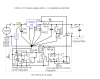
The circuit that I'm using generates a square wave.

You can get heatsinks to glue onto dip packages, though for a one off you could probably hack a standard 'sink to fit, and you could use some metal loaded epoxy to glue it to the chip, obviouslt making sure its away from the pins.

I was thinking about ways to attach a heatsink to the lm380, was unsure if glueing would have been an option. Can you recommend a suitable product for this?
 
Oops I had it you were making a sine, square on the other hand will produce less dissipation as the o/p devices will spend less time in the linear region, allthough an audio amp is in the linear region all the time to some extent, but its still a cheap source of an osc an o/p driver.

looks like I've used it all up now, however I got some araldite stuff from RS that contained magnetite, it was a version of araldite 2000.
You know for a one off you could file a bit of ally mix it in with some epoxy and do a test run on some scrap, I bet it'd work well.

https://uk.rs-online.com/web/p/epoxy-resins-adhesives/0850962/
 
Thanks Dr P

Back to my mc34063 STEPUP circuit. Looking to try IRFZ44N in place of the IRL2910, as it has lower RDS(on) However this is only with 10 volts gate-source voltage. Have been operating the STEPUP with 5 volt supply, which gives only ~4 volts drive for the MOSFET, works OK with IRL2910, but would not properly switch on the IRFZ44N.

I started looking at my lm386 diode capacitor STEPUP circuit. With 1 stage I could only get about 8 volts with 2 stages was able to get about 12 volts unloaded, or just over 10 volts with 10mA load. I decided to see if it would work at lower voltages. Works at 3 volts though only about 27% efficient. I'm curious to see how the CMOS 555 would compare with the lm386 at these voltages. I think the CMOS 555 would need an external pull up resistor as source current is only 10mA, though sink current is 100mA.

Anyway the lm386 circuit is adequate for what I am intending. I will post a circuit diagram shortly.
 
Ok.

In those circumstances you'd be better with a fet with a lower threshold, or as you have chosen a linear supply arrangement.

Just out of interest, if you had to use the '34063 and the 'z44's you could, the way to get around the issues would be to use a gate drive transformer, then you could have whatever drive voltage you wanted.
 
I have shifted the game plan somewhat. I have several old laptop power supplies with outputs of around 16~19 volts at 3+ amps. It occurred to me that I could make another variable power supply, by either stepping up from these voltages or stepping down.

I have came up with this idea for the stepdown circuit. The core of the circuit is an LM2575 simple switcher IC, just the application circuit from the data sheet. I have devised some additional circuitry to provide variable current limiting. Not 100% sure it will work properly in practice, but the basic idea seems sound. The only thing that concerns me is the possibility of instability in the additional control loop. The 100p capacitor in the error amplifier, was included to aid stability, though it's a bit of a shot in the dark for me as the mathematics involved are a bit over my head!

Opamp is LMC6482 dual CMOS rail to rail opamp.
 

Attachments

  • LM2575_Stepdown_With_Variable_Current_Limiter.png
    LM2575_Stepdown_With_Variable_Current_Limiter.png
    93.4 KB · Views: 1,052
Last edited:
Voltage feedback switchers like the 25nn series have a complex freq response, there are multiple poles and zero's to compensate for (although I think there is some internal comp), a current mode chip like a uc3842 is much more friendlier to design, but its not a monolithic chip the the 25nn.

I would simplify the circuit quite a bit, design the 25nn as though it didn't have current feedback, and just use the standard 2 resistors for voltage feedback, then design a current amplifier using the sense resistor your using, and connect the o/p of this to the feedback pin on the 25nn through a 1n4148 diode, so that when the current reaches the set point the op amp lifts the feedback voltage up against the 2 resistors and causes the chip to wind back on power a bit, if you use a slowish op amp like a lf358 you might get away without compensation, you dont need rail-rail as the '358 goes to ground and the feedback voltage is only 1.25v, make sure your grounds are good, looks like you know the score on that one looking at your schem.
Also 1m feedback resistors on a power circuit although it might work are not advisable, the system will be sensitive to noise and possibly supply ripple.
 
I would simplify the circuit quite a bit, design the 25nn as though it didn't have current feedback, and just use the standard 2 resistors for voltage feedback, then design a current amplifier using the sense resistor your using, and connect the o/p of this to the feedback pin on the 25nn through a 1n4148 diode, so that when the current reaches the set point the op amp lifts the feedback voltage up against the 2 resistors and causes the chip to wind back on power a bit, if you use a slowish op amp like a lf358 you might get away without compensation, you dont need rail-rail as the '358 goes to ground and the feedback voltage is only 1.25v, make sure your grounds a
Also 1m feedback resistors on a power circuit although it might work are not advisable, the system will be sensitive to noise and possibly supply ripple.

If I have understood you correctly, I was thinking of something similar. See attachment.
 

Attachments

  • lm2575_stepdown_with_Simpler_Current_limit.png
    lm2575_stepdown_with_Simpler_Current_limit.png
    63.6 KB · Views: 1,584
Theres a good chance of that working well.
The only concern is the gain of the op amp, at high gains stability might be an issue, with o/p currents over 100ma it'll probably be ok.
If you really want to go down to zero current limit then maybe a pot driven one end with a current source and the other end connected to the sense resistor would be better, the current source will add voltage depending on the resistance of the ilimit pot, then you could have the op amp gain down to around 25 instead of very high.
I'd still proto the circuit and see if it works.
 
It is and it isn't working. See attached test circuit.

Initially it was a little bit unstable with 150 ohm load connected across the output, the 1nF capacitor was added to the opamp feedback network and the circuit was stable again and limiting at around 35 mA with the test values in the diagram.

I then constructed a simple variable electronic load to allow for more comprehensive testing. When this was connected to the output of the circuit there was evidence of instability again ( output voltage won't settle ) I had a look at the lm2575 data sheet and it shows a 2200uF cap for the C2 position, I've been using 1000u. I also need to return the anode of D1 via its own wire to the star earth point. I got fed up with the circuit today ( didn't sleep well last night ) but I'll go back to it and address the issues I've considered. I forgot to mention that I intend to have two switchable current sensing resistors of 0R2 as before for 50 to 1000mA and a 2R sense resistor for 5 to 100mA, this will avoid the need for a very high gain amplifier.
 

Attachments

  • lm2575_stepdown_circuit_test_04_12_2015.png
    lm2575_stepdown_circuit_test_04_12_2015.png
    79.4 KB · Views: 541
Got it working now. Stupid mistake with the grounding arrangement was the problem. I had -Ve rail of the opamp sharing the same wire as the -ve of the output capacitors! When I returned the opamp -Ve by its own wire to the star ground point the circuit worked perfectly, with no need for compensation components. I am going to use the other 1/2 of the '358 as a comparator to activate a red led when the circuit is limiting.
 
I have now tested the circuit with variable current limiting and a current limit indicator. Seems to be working well. I have attached the schematic of the circuit tested today.
 

Attachments

  • lm2575_ps_with_variable_current_limit_05_11_2015.png
    lm2575_ps_with_variable_current_limit_05_11_2015.png
    103.1 KB · Views: 765
Cool, great to see you got it working.

Current limit leds for me are a bugbear, I have to get them to light just at the point of limit.

I'm not saying do this however if R2 was a low enough value you could replace d2 with a led and tweak the gain to compensate, then it will light as the circuit current limits, there will be a smidge of temp non linearity which if you were ott you could design out using the gain of the op amp.
 
Cool, great to see you got it working.

Thanks.

Current limit leds for me are a bugbear, I have to get them to light just at the point of limit.

I'm not saying do this however if R2 was a low enough value you could replace d2 with a led and tweak the gain to compensate, then it will light as the circuit current limits, there will be a smidge of temp non linearity which if you were ott you could design out using the gain of the op amp.

I thought about that led idea too but wasn't sure how well it would work. I tried using an npn transistor to activate the led but the switch on was very gradual. I ended up using a multiturn trimmer pot to set the threshold for the opamp based comparator at the point of just the tiniest drop in output voltage ( from the regulator ) by virtue of the current limiting signal.
 
I decided to try out an external p MOSFET switch with the lm2575 to try and improve effiency as the internal switch can drop as much as 1.7 volts.

It turned out to be worth the effort with efficiency of 93~94% being achievable.

I haven't included the current limiting add on yet. I'm somewhat concerned with stability issues given the increased gain due to the pmosfet operating in the common source mode.
 

Attachments

  • QuickCopperExport(1).png
    QuickCopperExport(1).png
    57.9 KB · Views: 505
The circuit looks well designed, and your right about the gain, the problem is that the circuit has a linear response as well as on/off, still it works ok in voltage mode.
Maybe apply the voltage off the sense resistor to one of the existing pfet driver trannys so that when it gets to 0.6v it holds the fet off.
I struggle a little with high side.
 
I struggle a little with high side.

Yeah it took a good mixture of planning and trial and error. I would like to utilise an n MOSFET on the high side, which means some means of generating a boosted +ve rail to properly drive the gate in order to fully utilise the very low RDS on. I was thinking also about the idea of replacing the freewheeling diode with an nmosfet, but not too sure about the driving arrangements to ensure that the high side and low side transistors aren't simultaneously conducting.
 
The simplest way to drive a nfet would be to use a gdt, you just need a 3e5 or similar torroid and a piece of cat 5 wire twisted and wrapped around, you can have whatever voltage you want adjusting the turns ratio, if you do go for a boost in drive voltage you'll need a protection zener from gate to source to prevent blowing the fet gate.
Synchronous rectification would increase the efficiency of switching and rectfying, however the extra power to run the sync driver might mess up your overall efficiency.
There are some modules on ebay that have a built in controller chip which drives a mosfet switcher and rectifyer, not sure what the no. is, probably wont take much finding, I think they have I limit too.
 
Status
Not open for further replies.

Latest threads

New Articles From Microcontroller Tips

Back
Top