Continue to Site

Welcome to our site!

Electro Tech is an online community (with over 170,000 members) who enjoy talking about and building electronic circuits, projects and gadgets. To participate you need to register. Registration is free. Click here to register now.

  • Welcome to our site! Electro Tech is an online community (with over 170,000 members) who enjoy talking about and building electronic circuits, projects and gadgets. To participate you need to register. Registration is free. Click here to register now.

Stepper Motor Ideas?

Status
Not open for further replies.

TheNewGuy

Member
Hey Everyone,
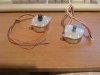
I have these stepper motors I pulled out of a printer, I was hoping you guys could give me ideas as to what I could do with them. Maby connect them to a computer and somehow control them, but after that??

Anyway, their model numbers are PM42L-048-SYE8 and PM42L-048-SYE9. It says NMB before the model numbers, I'm guessing it is the company that makes them.

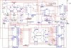
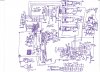
I found this datasheet, it is the closest thing I could find.

-TheNewGuy
 

Attachments

  • Motors.jpg
    Motors.jpg
    474.9 KB · Views: 1,492
Judging from the picture, the one on the left is bi-polar (four wires) and the one on the right is unipolar (6 wires). They use different driving techniques. Did they both come from the same printer ?
 
Judging from the picture, the one on the left is bi-polar (four wires) and the one on the right is unipolar (6 wires). They use different driving techniques. Did they both come from the same printer ?

Bi-polar vs. Unipolar? How should I use each?
 
Last edited:
Bi-polar requires an entire hbridge for each wire. Unipolar requires only a single transistor for each of the leads.
Stepper motor - Wikipedia, the free encyclopedia

6 wire unipolars are pretty easy to use, you tie the common's together and usually that's supplied VCC directly and then you use NPN transistor or MOSFETS to sink current in the correct pattern to cause the stepper to move.

Jones on Stepping Motors
**broken link removed**

You can also buy stepper motor driver which take care of the controlling for you. You can find this and plenty more information using Google, and searching the forums here as this topic has been covered many times. All the works pretty much been done, you just gotta look it up =)
 
Last edited:
For the bipolar stepper use the L6208 (ST semi). It can handle stepper motors up to 46V (starting at 8V) and 2.8A rms. It is manufactured in a DIP24 package and easy to use.

It just requires an external clock signal and different steady control signals.

The datasheet contains a full application on page 19.

Boncuk
 
I'm working on a circuit that uses a whole bunch of IC's to drive a stepper motor a certain distance (automatically) and can reverse the direction of the motor if it is necessary. I am going to use the circuit to run a bi-polar stepper (that I tore out of a scanner) to operate some vents that are on a housing unit covering my Wii. The vents cover a large fan at the top of the housing. I will try to post the schematic as soon as I finish, although it may be in several different parts, and if you're sure you can handle the horror:eek:
 
Here is the first part of the circuit (the driver):

If you would like to request the circuit (hand drawn and less confusing) send me a message. I'll reply as soon as I can.
 

Attachments

  • Stepper ex1.JPG
    Stepper ex1.JPG
    146.6 KB · Views: 2,103
I'm working on a circuit that uses a whole bunch of IC's to drive a stepper motor a certain distance (automatically) and can reverse the direction of the motor if it is necessary.
Sounds like another waste of time in that you can buy one for less then you can build it. Why would you want to do that ?

3v0
 
Last edited:
Sounds like another waste of time in that you can buy one for less then you can build it. Why would you want to do that ?

3v0

maybe I like wasting my time with redundancy... oh who am i kidding, i cant afford any of the parts from online (being 17 with no credit card) and radio shack does not carry the parts i want. besides i need the circuit to open and close automatically without human inter action or computer interaction, and this is the only way i know how. bellow is the what i hope to be the final circuit, but i constantly find things that need to be changed to make it work right.
 

Attachments

  • scan0001.jpg
    scan0001.jpg
    1.5 MB · Views: 12,192
Honesty like that goes a long way around here. At least it does with me.

But I have to warn you that it is harder to get help with "That Sort" of project.

I do not see where you will be saving any money unless you have a free supply or logic gates.

Are you interested in learning to program ? Or maybe already can and would like to learn to do so using PICS ?

3v0

The circuit is an experiment and yes, for the experiment I have almost unlimited logic gates, this is just for proof of concept.
 
Just as an experiment, I want to connect one of these stepper motors to my compuer, and be able to control it by my computer. From what I've reserched, the unipolar stepper motor would be easer (right?).

I've looked up schematics and I found this one. I'm guessing this one would be the easiest to build?

What I don't know if it is the cheapest?

Would you recommend this for a beginner?
 
That's pretty basic, hard to get more basic actually. It will work, depending on how much current the stepper needs however your real problem is going to be the software side of tings. Modern windows PCs need a special driver installed to directly access the parallel port, and you have to write the software for it. It'd be easier to do with Linux on the software/hardware side but that requires that you have a decent amount of programming/software knowledge.
 
Hey,

this is my first post here, so, hello everyone!

@ TheNewGuy: Driving steppers may really seem complicated at first (H-Bridges, unipolars, bipolars, microstep, full step, etc, etc), but it's really, reaaaally simple. A first experiment that helped me see what should I do to drive a stepper was connecting little push-buttons to the winding terminations and pressing them until I figured out myself how the whole blab of full-step and half-step worked.

I think you shouldn't try to connect the motor to the PC at first. Why do that? Too much complication, too much spurious problems... Keep it simple, pal. Use a PIC, an 8051, whatever microcontroler you like.

You could, for example, attach five buttons to the uC: one for stepping one step clockwise, the other for stepping one step counter-clockwise, one for stepping clockwise continuously , one for stepping continuously counter-clockwise, and the last one to stop the whole apparatus.

It's a nice and simple programming exercise.

The only hardware you may need is an H-Bridge, if you decide to play with the bipolar; or four transistors (and diodes), if you use the unipolar.

For me, the simplest thing to be done is to buy the hefty L298N (an integrated H-Bridge - works with Bipolar and Unipolar steppers, not too expensive and really easy to find) and you are ready to play ball.

Digi-Key - 497-1395-5-ND (Manufacturer - L298N)

Hope it helps. My suggestion sure isn't something useful, but it will teach you the basics of a stepper, and with the code you make you could design things a bit more complicated. A friend of mine, for instance, made a remote-controllable venetian blind with two-steppers and an old AT89S52 for an assignment at college.


Castilho
 
...You could, for example, attach five buttons to the uC: one for stepping one step clockwise, the other for stepping one step counter-clockwise, one for stepping clockwise continuously , one for stepping continuously counter-clockwise, and the last one to stop the whole apparatus....

Hello,
Yea, I think you're right. Too many little problems, could you draw it out so I could see it visually, or just elaborate?

Thank you very much!

EDIT: What's a uC?
 
Last edited:
6 wire unipolars are pretty easy to use, you tie the common's together and usually that's supplied VCC directly and then you use NPN transistor or MOSFETS to sink current in the correct pattern to cause the stepper to move.

The links helped a lot, but how would this look in a schematic? I'm having trouble laying it out.

I've been reading it, but would you use more than one transistor? Because minus the two commons you are left with 4 wires? Right?
 
Status
Not open for further replies.

Latest threads

New Articles From Microcontroller Tips

Back
Top