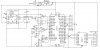
I've attached the schematic for my project. I'm having problems with the Stepper motor driving part. The PIC's Port D is being used to drive the 8 wire stepper motor (Connected in Unipolar config) through a ULN2003.
The Stepper Motor's wires are wired to a socket which plugs into J5 (seen on the schematic).
J5 Pin Number - Motor Wire Color
1 - Orange
2 - Black
3 - Red
4 - Yellow
5 To 8 - The Common wires as seen in the other picture I've attached.
I'm sending out the hex values: 99, 55, 66, AA in that order on Port D.
I tested the circuit by constructing just the Stepper motor part on a Bread Board. The motor just shudders, but does not run.
I know for sure that the PIC is working and giving out the right sequence, I verified this by connecting LEDs to the port.
Another thing is also happening for sure: The ULN is baking. Within a matter of seconds of switching the circuit on, the ULN is not touchable.
Figuring that the sequence could be wrong, I tried all possible combinations of the mentioned hex values. All of them gave me the same result. I can feel a rhythmic beating inside the motor when the circuit is ON. I tried changing ULNs also. I also tried giving high delay times between steps (upto a half second)
What could the problem be? Too high a current flowing thru ULN? But why? Isn't the ULN's job here just to amplify the signals coming from the PIC, to magnetise the coils? It doesn't need to source any current as the common wires of the stepper motor r connected directly to the power supply, right? Am I missing a point here?
But still, why isn't the motor running? Is there any error in the driving circuit? Is there a better way of driving a Stepper Motor?
The Motor has a 4V, 0.5A rating.