Continue to Site

Welcome to our site!

Electro Tech is an online community (with over 170,000 members) who enjoy talking about and building electronic circuits, projects and gadgets. To participate you need to register. Registration is free. Click here to register now.

  • Welcome to our site! Electro Tech is an online community (with over 170,000 members) who enjoy talking about and building electronic circuits, projects and gadgets. To participate you need to register. Registration is free. Click here to register now.

555 driving N mosfet

MrDEB

Well-Known Member
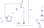
Working on a method to have an adjustable flash on an LED neon strip.
Have attached the schematic for the test circuit, plan to use a 7805 to power the 555 but testing with a 9v battery I get 4 volts on the 555 output.
The issue is the gate has a maximum of 4v on the gate.
thinking of a voltage divider or Zener diode on the gate to avoid applying too much voltage to the gate.
I show 2 LEDs but D3 is just for testing. D2 will be a 12v LED neon strip. the 9v will be 12 v.
and yes the breadboard circuit works as showen
 

Attachments

  • 555 and mosfet.png
    555 and mosfet.png
    34.1 KB · Views: 192
Actually the threshold Vt=Vgs(th) is 2 V min , 4 V max @ 0.25 mA @ 25'C which equates to R=V/I = 4V/0.25mA = 16 kohms max, with Vgs=4.

Then plots are for nominal thresholds
1685829838977.png
 
The datasheet of an old 555 with a 9V supply, shows that its output goes as high as +7.6V when it has a 20mA load.
You might have measured 4VDC but the AC signal goes up and down over and over.

The datasheet of an IRF520 shows a gate-source threshold voltage of from 2V to 4V. The threshold voltage is when it barely turns on and conducts only 0.25mA which is almost nothing.

The diode in your 555 oscillator circuit does nothing because the discharge pin 7 has nothing to make it go high and it goes low at the same time the output pin 3 goes low.
 

Attachments

  • 555 oscillator.png
    555 oscillator.png
    29.8 KB · Views: 123
Just a future caution. When choosing gate drive resistor there are conflicting
decisions to be made.

One is current needed by source (555 in your case) and its limits. High currents
into/out of pins can cause faults in device operation.

Two is switch device dissipation. Sim below shows R1 stepped from 10 ohms
to 1K, 3 steps. One can see dramatic rise in MOSFET Pdiss when R1 high because of slow
rise time keeping MOSFET in saturation region where Vds high relative to when
MOSFET hard on and Vds is lowest. But at low values of R1 we get high currents
needed from MOSFET gate drive source device.

1685874105468.png


1685874174286.png


Regards, Dana.
 
Last edited:
I am BASICALLY LOST with this post. I need more understanding about MOSFETs in general
What is pdiss?
planning to use a 7805 to power the 555 instead of the 12 volts so need to measure voltage on pin 3 with 5 volt supply
 
Pdiss = power dissipation in the MOSFET itself. Two components, the power
dissipated driving gate C and the power in the Drain Source, eg. Vds x Ids.

If high enough MOSFET has to be cooled, usually with a heat sink. Or alrge copper
area on PCB which it is bolted to.


Regards, Dana.
 
Last edited:
With that low operating voltage, you can do some things to assure operation.

3. Change to the CMOS version of the 555. Its output swings much closer to the rails.

2. Delete R1. There is no reason to throw away 9% of your drive voltage.

1. Change to a "logic-level" MOSFET. These can reach full enhancement (fully "on") with a much lower gate voltage.

4. Put R4 and D3 in parallel with R5 and D2. Let the power part do the work. Taking this load off the 555 output will increase the peak output voltage to the MOSFET gate.

ak
 
Last edited:
I would be cautious about having the LM555 output tied directly to a large cap,
the MOSFET gate, to insure peak current does not load down 555 internal supply rail
or dump charge into the ground rail causing logic errors, at minimum for either
source or sink case.

The output doe not have a short circuit rating, so the only thing limiting peak
current would be ESR of any C tied to output. Could incur part failure or reduced
reliability.


Regards, Dana.
 
The datasheet of an old (51 years old) 555 shows a graph of the output voltage with different load currents.
With a 5V supply and driving a 20mA LED, its output will be a high of only +3.6V which is too low to turn on an IRF520 Mosfet. Your Mosfet schematic has a 1k and 10k voltage divider that produces a gate voltage of only +3.27V.
The IRF520 needs a gate voltage of at least +7V for all of them to turn on well.

In the first post you said you want "an adjustable flash". What do you want to adjust? The circuits you showed do not have an adjustable number of flashes per second, instead they use PWM to vary the duty-cycle (on time vs off time) or if the speed of the flashes is high enough that we see steady light without flashing then the circuit is an adjustable light dommer.

Here are some more circuits from the 555 tutorial:
 

Attachments

  • PWM from 555.png
    PWM from 555.png
    69.4 KB · Views: 126
#7 If you understand the internal schematic of 555 uses an open collector switch for the DISCHARGE output, then you will readily see that is your main difficulty.

As audioguru said in #7 , you are missing the pullup resistor.

That value should be lower than the Pot value but not so low that the transistor cannot pull down near < 50mV This is generally 5 % of the base resistor when driven from the same voltage as the pullup. It could be 2% to 10% of Rb but that is my guesstimate..

I disagree with the use of the diode, because you want the average voltage of the discharge output to be 50% of Vcc +/- 2% or so then you will always get 50% duty cycle. The diode raises the lower level by 0.6V which offsets the average DC level of the triangle wave which would want to be 50% as the toggle thresholds for set/reset are 1/3 and 2/3 which means the hysteresis is 50% of Vcc.

Coincidentally this the same hysteresis used in CMOS Schmitt Triggers, although the threshold voltages are not controlled by resistor ratios but by Vgs(th) which have a 50% tolerance.

Here you can see your schematic shown in a more logical arrangement with the pullup and without the so-called 50% improvement tweak diode, which I think is no help

Notice I am using 15V so the thresholds are nice round numbers 5V ,10V and the average is 7.5V. Then examine the plots and look for the average Vdc and the duty cycle error.
1685919302512.png
 
Last edited:
It will work the same with 5V more or less as everything works from R Ratios for thresholds. The only source of error is the peak DISCHARGE differences from Vcc and 0V. Same f and same 50% duty cycle if these R values are used.
 
OOPS

I zoomed in on my schematic above which was copying your connections to the pot and then realized I had a gap, a missing connection that works better with my mistake.

Here is my same simulation link below but I cleaned up the schematic.

See if you can spot the gap in the connection above not needed.

I also swapped ends on the Pot to increase f with slider to the right.


rev B https://tinyurl.com/2gl42xy6
 
Last edited:
A more precise square wave audio oscillator on 5V could use a Rail-to-Rail CMOS Op Amp.


With any pot you can expect a tuning ratio from Rmax : Rmin = 200 : 1 roughly, depending on construction, and thus the same in frequency ratio.

The above parts provide 50 Hz to 10 kHz.

With 200k/(1M +100k) * (Vout-2.5V) = 0.45V hysteresis providing a smaller change in threshold or a triangle input of 0.45V and the Pot R providing the current limiting to the cap. with dV/dt = Ic/C so that for dV = 0.45 then dt = the half cycle.

1685931961137.png
 
Last edited:
well I got this circuit connected to a 5m/16.4ft of led neon strip
It flashes as it is supposed to.
The problem is the MOSFET gets warm (stopped measuring at 130 degrees) and I show a 2amp draw.
specs are 12v .8A/meter 9.5W/meter (5m = 48W)
as my schematic shows, I added a 7805 voltage regulator.
looking back at post #15 I need to use a 7555 and/or remove the 1K and 10K resistors?
Does that sound about right?
First remove the resistors, and measure then?
 

Attachments

  • 555 and mosfet.png
    555 and mosfet.png
    34.1 KB · Views: 121

Latest threads

New Articles From Microcontroller Tips

Back
Top