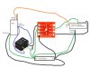
Continue to Site

Welcome to our site!

Electro Tech is an online community (with over 170,000 members) who enjoy talking about and building electronic circuits, projects and gadgets. To participate you need to register. Registration is free. Click here to register now.

  • Welcome to our site! Electro Tech is an online community (with over 170,000 members) who enjoy talking about and building electronic circuits, projects and gadgets. To participate you need to register. Registration is free. Click here to register now.

space balloon / circuit help / awful diagram

Status
Not open for further replies.
kchriste said:
It is possible, but more likely because the opto doesn't have enough drive capability to activate the relay. Looking at the schematic of the opto PCB, I see some 2n2222 transistors being driven via an isolator and 10K pullup resistor. The 10K resistor means that the transistor is only getting apx 0.7ma of drive current when the battery voltage is 7.5V. The 2n2222 won't have enough beta (gain) to turn fully on (saturate) so won't apply the full voltage across the relay coil. You could test this by measuring the voltage across the relay coil with your volt meter. It would be best to have the radio turned off because the RF will probably cause the meter to give a false reading.

When I measure the voltage between OUT1 and the positive lead on the battery I get 7.4 volts (actually its a little over 8 if fully charged) and I get 10 amps. Looking here - https://www.electro-tech-online.com/custompdfs/2009/11/G5V-1.pdf I need about 20 amps at 7.4 volts. It seems clunky but I guess I could drive OUT1 and OUT2, wire them in series, boost the voltage to 15V and then the 10 amps would drive the coil. There must be a more elegant way :)

The radio also blanks out the GPS when transmitting; not a big deal as it only transmitts every 4 or 5 minutes. Oddly the chip on the gumstix puts off exactly the same frequency as GPS signals so you will see a second post on how to make a lightweight RF shield to keep the GPS antenna away from the gumstix 'jammer'


kchriste said:
If the voltage is too low (Less than 5V) then we could add a transistor to boost the current. What types, if any, do you have on hand?

I can get whatever I need from the electronics across the road, but I think its amps I need, not volts.

kchriste said:
It would go across the relay coil with the stripe facing the (+) battery side. Any of the 1N400x (Where x is a number) diodes will work. So will the common 1N4148 or 1N914.

I do have a few diodes so I'll give it a shot. To be clear, I would just wire the stripe side to the relay pin that goes to the positive terminal on the battery and the other end of the diode to the other relay pin. In essence, both the diode and the wire to the + on the battery will be connected to the same leg on the relay?
 
When I measure the voltage between OUT1 and the positive lead on the battery I get 7.4 volts (actually its a little over 8 if fully charged)
That point is essentially across the relay coil and also across HV and OUT1 on the opto. Since the coil only needs 5V to activate it, 7.4V should be OK even if it is a little high. I suspect the opto may be shorted as the voltage would be typically lower than the full battery voltage. You should have heard the relay click when the voltage first appeared.
and I get 10 amps. Looking here - https://www.electro-tech-online.com/custompdfs/2009/11/G5V-1-1.pdf I need about 20 amps at 7.4 volts.
Where do you get 20 amps from? The relay coil only needs 25ma (That's 0.025 amps) @ 5V to work. If you've put your meter across that point on the "Amps setting" and read 10 amps, then you've damaged the opto by doing so. The meter should only be put in series with a load when on the amps scale. Never in parallel in amps mode! If the OUT1 terminal is damaged, you could switch things over and use the OUT2 and IN2 terminals instead.
I do have a few diodes so I'll give it a shot. To be clear, I would just wire the stripe side to the relay pin that goes to the positive terminal on the battery and the other end of the diode to the other relay pin.
That is correct:
 

Attachments

  • diag.jpg
    diag.jpg
    76 KB · Views: 373
Last edited:
That point is essentially across the relay coil and also across HV and OUT1 on the opto. Since the coil only needs 5V to activate it, 7.4V should be OK even if it is a little high. I suspect the opto may be shorted as the voltage would be typically lower than the full battery voltage. You should have heard the relay click when the voltage first appeared.
Where do you get 20 amps from? The relay coil only needs 25ma (That's 0.025 amps) @ 5V to work. If you've put your meter across that point on the "Amps setting" and read 10 amps, then you've damaged the opto by doing so. The meter should only be put in series with a load when on the amps scale. Never in parallel in amps mode!

oops... I meant 20ma. Right now I am getting 10ma at 8volts between OUT1 and HV (or power lead on the battery) I got 20ma by interpolating.
 
Last edited:
oops... I meant 20ma. Right now I am getting 10ma at 8volts between OUT1 and HV (or power lead on the battery) I got 20ma by interpolating.
If you get 8V there when the relay coil is also connected, and the 8V can be turned off and on by the Gumstix, and you hear the relay click, then everything is OK.
 
If you get 8V there when the relay coil is also connected, and the 8V can be turned off and on by the Gumstix, and you hear the relay click, then everything is OK.

Well that is the problem, 8volts @ 10ma is not enough to click the relay. I can hear it click if I use a small battery I made that puts out 3.7V and 80ma.

The gumstix does indeed turn the 8V / 10ma on and off as expected. I just need about 10ma more to get the relay to click over.

Hopefully that makes sense and thanks for your help with this. Let me know when you decide to build a balloon project and I'll be happy to help out :)
 
Last edited:
Add a PNP transistor like this to boost the current:
 

Attachments

  • diag.jpg
    diag.jpg
    80.1 KB · Views: 192
Thanks, I will get the parts this morning and give it a go this afternoon. I'll post the result as well.
 
cynic, you have to satisfy ALL portions of the code, you can't just pick one and say it's okay.

You conveniently snipped the portion of the code that your balloon violates.
You still have to satisfy EVERY condition. Not just the ones you feel like.


Sceadwian

You did all that you could do, to warn him!

You did your best, and are held in great esteem for your efforts.

Keep up the good work.

God Bless...
 
Add a PNP transistor like this to boost the current:

I finally got some free time this morning and wired things up. That works. Current was boosted to 30milliamps which will work just fine.

Thanks again for the help and feel free to ask if you have balloon questions:)
 
Ok - Next question....


As I mentioned; the gumstix chip just happens to run at a speed that is a harmonic for GPS signals and I have found that the gumstix is in effect a GPS jammer. I have also found the 5 watt radio transmitter pretty much blanks out the GPS signals as well. That's less of an issue because it only transmitts for a few seconds every 5 minutes.

As a result I need to have an RF shield between the flight computer and the GPS antenna. As I understand an RF shield it basically absorbs or blocks energy. Using that same diagram.... could I get some sort of wire mesh and ground it to my battery? Would that be bad? Would the ground help?

Suggestions?
 
For testing you can just try wrapping it in tin foil and connecting to the system ground. Mesh should work as well.
 
For testing you can just try wrapping it in tin foil and connecting to the system ground. Mesh should work as well.

Sceadwian,

Thanks again for the help on this. Tin foil did the trick. For those interested in a brief writeup in progress on my project you can see it here - **broken link removed**

It's not completed. Post launch and assuming my balloon does not end up in the atlantic ocean I'll post a link to some HD movies and I'll finish the writeup that includes necessary perl scripts that put everything together.
 
Status
Not open for further replies.

Latest threads

New Articles From Microcontroller Tips

Back
Top