Continue to Site

Welcome to our site!

Electro Tech is an online community (with over 170,000 members) who enjoy talking about and building electronic circuits, projects and gadgets. To participate you need to register. Registration is free. Click here to register now.

  • Welcome to our site! Electro Tech is an online community (with over 170,000 members) who enjoy talking about and building electronic circuits, projects and gadgets. To participate you need to register. Registration is free. Click here to register now.

Some general questions,...

Status
Not open for further replies.

tribaloverkill

New Member
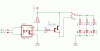
Hi. I'm new here and new to this whole making of electronic "stuff". I have this little project I'm trying to get underway. Basically, I want to wire up some UV LEDs for the inside of my computer. The only thing is that I want them to flicker along with the HDD LED. I know I just can't wire a string of LEDs right to the HDD jumper. I'm pretty sure I need a relay with a secondary power source. I want to wire a 3-way switch also that will allow me to turn them off, on, and strobe. I know how to wire everything. I just dont know what to use. I don't know jack about power ratings and stuff like that so I need some help. First,... some stuff I do know. My PC has a 500w PSU with +3.3VDC@28A, +5VDC@30A, +12VDC@34A. The HDD jumper when active gives off ~1.9V@.0 - .1A. I went to Radio Shack and picked up some stuff. I don't know if I can use them but I got them to get the info off the back that I don't understand. I got a 3-way and a 2-way switch. The both have the same ratings, "Rated 10A@125VAC, 6A@250VAC". Can I run the power from my PSU through this? I dont know how to calculate the rating in VDC if I even have to. I think I can but I am not sure. I also got a 12VDC Reed Relay that is normally open. Some info on that,... "Voltage:12VDC, Coil Resistance: 1050 ohms, Contact rating:1A@125VAC, Nominal Current: 11mA". what does all that mean? I think the voltage is what operates the relay or closes it. Contact rating is how much power I can run to it or through it once the relay is closed. Nominal Current is the power thats eaten up by the relay? Is any of that right? How do I know what the equiv for the A@VAC?!?!? Am I using the right relay for the job? I need a realy that can keep up with the HDD jumper and will live for some time and not die out. Thanks.
 
I think the voltage is what operates the relay or closes it. Contact rating is how much power I can run to it or through it once the relay is closed. Nominal Current is the power thats eaten up by the relay? Is any of that right?
that is all correct ..
is the LED comming from the hard drive or the motherboard..?
 
Basically,... the the hard drive jumper gives off 1.9@.1A which is just enough to power one crappy LED. I want several series of LEDs to blink along with the hard drive activity. The jumper is on the motherboard. I want the jumper to operate the rely and then have a secondary power source run through the relay to power the rest of the LEDs. I went to Radio Shack again and there was an engineer there and he said the my PSU would fry the switches and relay I got. the relay wont even work off of the jumper seeing that there isnt enough power to operate the relay. So I need a relay that operates at or under 1.9v and can tolerate either 5v@30A or 12v@34A. I don't know what I need:(
 
Ummm,... I have to read up on what that is but that doesnt help me. I need to know what kind of relay I need to get this done. Do you know of any?
 
That HDD pin has got to be a 5V logic level with a series resistor already on its board. The main question is if it's a high side or low side drive... I'm assuming it's a sane low side drive.

You can use the signal to drive either a N-channel MOSFET gate or an NPN transistor's base. The base may require another transistor, but I think the resistor on the supply is sufficient based on what you said. It would probably go up to 15 mA or so. From there, you get a +5V tap off the power supply cable and put the LEDs each with their own series resistor all in parallel, one end on +5V, the other on the drain/collector. You can drive any number of LEDs like this.
 
i just measured an Led on a motherboard..it read..
2.08V while connected to the motherboard
but it measured 4.90 v at the connector..
perfect for the gate of a N-channel FET..or the input to an opto-isolator..
 
Well,... I didnt measure the volts right at the pins but instead I measured the volts by pulling away the shrink wrap by the LED. Would that make a difference?
 
sure it makes a difference..if you carefully remove the connector ..and carefully measure the voltage at the LED pins on the mother board.. it will be around 5 Volts..
I wouldent meaure current at the LED terminals .., it is just something i wouldent do..
 
tribaloverkill said:
I want to wire up some UV LEDs for the inside of my computer. The only thing is that I want them to flicker along with the HDD LED. I know I just can't wire a string of LEDs right to the HDD jumper. I'm pretty sure I need a relay with a secondary power source.

How many led's are we talking about? Do you have information about the led's you want to use (forward voltage and forward current?).
I wouldn't use a relay as it will be to slow to follow the blinking of a harddrive led, it will also wear down quickly because it has to switch so often.

As samcheetah said, an optocoupler is the way to go.
 
Product Description

Emitted Colour : ULTRA VIOLET
Size (mm) : 5mm T1 3/4
Lens Colour : Water Clear
Peak Wave Length (nm) : 385 - 395
Forward Voltage (V) : 3.2 ~ 3.8
Reverse Current (uA) : <=30
Luminous Intensity Typ Iv (mcd) : Average in 2000
Life Rating : 100,000 Hours
Viewing Angle : 20 ~ 25 Degree
Absolute Maximum Ratings (Ta=25°C)

Max Power Dissipation : 80mw
Max Continuous Forward Current : 30mA
Max Peak Forward Current : 75mA
Reverse Voltage : 5~6V
Lead Soldering Temperature : 240°C (<5Sec)
Operating Temperature Range : -25°C ~ +85°C
Preservative Temperature Range : -30°C ~ +100°C

Thats the specs for the UV LEDs I have. I have to read up on this optocoupler. What is it and what does it do?
 
you can add more led's in parallel with the 3 on the drawing, all of wich need their own 470 series resistor.
you need to get the 12V and ground on the secondairy side of the optocoupler from a power connector (the ones you plug into your cdrom or harddrive)

Black is GND - Yellow is 12V

The 2N5306 should do fine upto 50 leds
 

Attachments

  • hdd.gif
    hdd.gif
    18.8 KB · Views: 489
Wow,... you guyz are great! Let me read about the optocoupler and then Im going to ask some questions about the drawing, if I even have any after reading. Thanks!
 
Status
Not open for further replies.

Latest threads

New Articles From Microcontroller Tips

Back
Top