Continue to Site

Welcome to our site!

Electro Tech is an online community (with over 170,000 members) who enjoy talking about and building electronic circuits, projects and gadgets. To participate you need to register. Registration is free. Click here to register now.

  • Welcome to our site! Electro Tech is an online community (with over 170,000 members) who enjoy talking about and building electronic circuits, projects and gadgets. To participate you need to register. Registration is free. Click here to register now.

Solder iron not hot enough for PC board

Status
Not open for further replies.
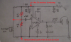
I notice that the Nuts and Volts circuit has an unfiltered Zener diode to power the electret mic. Don't they know that a Zener diode is a noise source?

Most electret mics pickup sounds and background noises from all around, then a dish is important to concentrate the pickup from straight ahead.
The dish must be fairly large to pickup low audio frequencies.
 
This is the LM386 circuit I built 4 or 5 years ago. I plugged in my new ear phone then connected the 9v battery I can hear everything better than hearing aids. I notice the circuit had no 10uf capacitor connected to pin 1 & 8 so I soldered a cap there are tested it again. WOW it picks up sounds from outside right through the walls of the house. There is no volume control it is ON all the way all the time. Don't ask why two 1K resistors are in series with capacitor between them it must be a mistake I did 5 years ago. I decided to change it I replaced the 1K resistors with a 10K and it works better. This works so good all it needs is a parabolic reflector there is very little noise or static. Mic is very sensitive & directional if I aim it down the road I can hear a car coming before I can see the car 1/4 mile away. When I unhook battery amp keeps working about 3 seconds until caps go dead.

Now that this amp works I know the electret mic works so I swapped mic with the mic on the chinese LM386 and it still does not work very well. I need to study this chinese circuit to figure out what is wrong.

**broken link removed**
 
Last edited:
The two 1K resistors are in series with capacitor between them are needed. The resistor on the right and the capacitor filter power to the microphone. The resistor on the right should be 10k and applies current to the Jfet inside the electret mic.

You have an extra un-needed capacitor at pin 3.

Without knowing the impedance of the earphones then the output capacitor value is a wild guess.
 

Attachments

  • LM386 again.png
    LM386 again.png
    111.8 KB · Views: 87
I changed circuit to this. I have not removed capacitor on pin 3 yet I wanted to test is first.

How are you doing attachments?


**broken link removed**
 
You removed the 1k resistor and capacitor that filter power to the mic. Then when there is some audio, the battery voltage will jump up and down a little, which enters the input of the amplifier and is amplified 200 times, then going around and around producing a putt, putt, putt, putt sound.

Why do you have two 100uF capacitors parallel with the battery?

You will not notice when the extra 0.1uF capacitor at pin 3 is replaced by a piece of wire because the simple calculation with 1 divided by (2 x pi x the capacitor x resistor values) show that it cuts low frequencies below 32Hz.

The headphones ad shows absolutely no detailed specs. 20Hz to 20kHz is missing the deviation. Plus and minus 20dB is terrible. Plus and minus 3dB is hifi. Also the very important impedance is not stated.

To attach something, I click on Attach Files, browse for my file and click open, then post my reply and it automatically becomes a thumbnail like this:.
 

Attachments

  • Audioguru avatar.jpg
    Audioguru avatar.jpg
    9 KB · Views: 85
You removed the 1k resistor and capacitor that filter power to the mic. Then when there is some audio, the battery voltage will jump up and down a little, which enters the input of the amplifier and is amplified 200 times, then going around and around producing a putt, putt, putt, putt sound.

Why do you have two 100uF capacitors parallel with the battery?

You will not notice when the extra 0.1uF capacitor at pin 3 is replaced by a piece of wire because the simple calculation with 1 divided by (2 x pi x the capacitor x resistor values) show that it cuts low frequencies below 32Hz.

The headphones ad shows absolutely no detailed specs. 20Hz to 20kHz is missing the deviation. Plus and minus 20dB is terrible. Plus and minus 3dB is hifi. Also the very important impedance is not stated.

To attach something, I click on Attach Files, browse for my file and click open, then post my reply and it automatically becomes a thumbnail like this:.

I do not understand your replies? Do you want 100uf cap next to 10K resistor? Do you want 10K gone? Do you want a 1K resistor too? Do you want both 1K resistors again? Do you want .1uf cap connected to pin 3.? Can I test earphones with VOM or LCR meter to learn anything? 100uf cap next to 10K resistor is still in parallel with the other 100uf cap.? Reason two 100uf caps are in parallel is I probably did not have a 200uf cap when I built this circuit 5 yrs ago. This is what I have now. Look there are two 1uf caps in series on pin 3.?

100_2584.JPG
 
Last edited:
I have not changed anything in the circuit I only moved R1 and C1 to a different place on the drawing. I think C2 needs to be removed. I have not changed R2 to a variable resistor yet. I have learned if I change C7 from 47uf to 100uf circuit has more low Hz then changing it again to 250uf it has more low Hz. Low Hz is noticeable with and without my hearing aid. At the moment C7 is 100uf it gives the circuit more base sound. I read online high Hz is lost with distance, people talking 1/2 mile away low Hz travels farther and high Hz is lost, so I think for a listening device C7 should be 47uf or lower, maybe a selector switch to 5 different caps will be helpful.

I hooked up my 40 year old circuit with a tiny 2" x 3" speaker and 9v battery to compare to this new circuit and the new circuit works better far as I can tell using this small speaker. Next I need to look for a 40 year old 8" speaker I may still have one. Next I want to replace the transformer and speaker with a electret mic to compare. I think the new circuit will still be the winner.

100_2586.JPG
 
You had it almost correct before.
Now the 1k resistor is missing that is part of a filter that feeds the 100uF capacitor to smooth the power feeding the mic's 10k resistor.
Before the 100uF capacitor parallel with the battery was 1000uF but the circuit will work fine with 100uF until the battery voltage gets low.

The LM386 already has an internal resistor at pin 3 so the 100k resistor is not needed and the extra 0.1uF input capacitor also is not needed.

You will be sorry that the volume control is missing. A motorcycle or jet airplane will deafen you and might destroy the earphones.

An earphone or speaker can have its resistance measured with a multimeter. An earphone with a 32 ohm impedance will measure about 28 ohms.
Then the two earphones in parallel will measure 14 ohms DC which will be 16 ohms impedance.
You draw the earphones in series instead of in parallel. Then they will sound odd because they will be out-of-phase.

I do not draw schematics with a dark grey background. Instead I copy the datasheet and paste it into Microsoft Paint program. I also copy and paste other parts to add to the 1st copy.
 

Attachments

  • LM386 again and again.png
    LM386 again and again.png
    511.5 KB · Views: 92
Your dark schematics continue to show error after error.
I commented on your 5 years old circuit.

Since the tone sounds change with distance then most people would design the circuit to produce all frequencies evenly then add a simple tone controls circuit to adjust the tones whenever you want, however you want.

Your volume control wired to short circuit the mic is also a tone control because it doubly reduces the levels of bass sounds when it is turned down.

Remember I told you the 1/(2 x pi x R x C) formula for the cutoff frequency? Then a 47uF capacitor that feeds an 8 ohm speaker passes high frequencies but cuts 1/(2 x pi x 8ohms x 47uF)= 426Hz and lower so there will be no bass sounds. 470uf will sound fairly good and 1000uF will sound very good if the sound source and speaker are hifi.
 

Attachments

  • LM386 again more.png
    LM386 again more.png
    663.3 KB · Views: 88
You had it almost correct before.
Now the 1k resistor is missing that is part of a filter that feeds the 100uF capacitor to smooth the power feeding the mic's 10k resistor.
Before the 100uF capacitor parallel with the battery was 1000uF but the circuit will work fine with 100uF until the battery voltage gets low.

The LM386 already has an internal resistor at pin 3 so the 100k resistor is not needed and the extra 0.1uF input capacitor also is not needed.

You will be sorry that the volume control is missing. A motorcycle or jet airplane will deafen you and might destroy the earphones.

An earphone or speaker can have its resistance measured with a multimeter. An earphone with a 32 ohm impedance will measure about 28 ohms.
Then the two earphones in parallel will measure 14 ohms DC which will be 16 ohms impedance.
You draw the earphones in series instead of in parallel. Then they will sound odd because they will be out-of-phase.

I do not draw schematics with a dark grey background. Instead I copy the datasheet and paste it into Microsoft Paint program. I also copy and paste other parts to add to the 1st copy.

OK your saying R1 is left of C3, 1K resistor is right of C3. I added numbers to the drawing it makes it easier to explain.

C8 or fine. I have a 1000uf I to replace C8. I have about 30 of these meter shows the real value is 830uf to 902uf most are about 850uf. I have several 470uf one of them tests 471uf. I have more 470uf I only tested 1. TWO 470uf in parallel are physically smaller than 1000uf. Voltage rating only needs to be 16v or 25v.

I am going to put a 100K volume control on this circuit, I already tested it with a volume control but not permanently added it to this circuit yet.

Ear phones are stereo only 1 ear is connect. I need to solder the other terminal so both ears work. I think I can solder these either series or parallel I need to test it with the meter.

I think I have correct correct now?


1/(2 x pi x R x C)

R= ear phones 2000 ohms

C = capacitor 47uf = .000047

1 (2 x 3.14 x 2000 x .000047) = 1 ( .59032) = 1.69Hz is this correct or did I do something wrong?


100_2587.JPG
 
Last edited:
Circuit has been changed and it works good. I decided to use 7 AA batteries instead of the 9v battery, it is much louder. The 9v battery tests 9.07v .57a. The AA batteries test 11.43v 2.35a. Ear phones test 32 ohms and 33 ohms also .118uh and .120uh. If I change wiring on the phone jack I can have 2 earphones is series or parallel. Experimenting outside I hear and airplane in the sky but cannot find it, it is sunny day with clear sky. I can hear construction workers 200 yards away talking but not loud enough to hear what they are saying. I learned with volume correct for my right ear then rotated head phones 180 degrees it is not loud enough for left ear but when I turn volume up I can make it loud enough to hear perfect.

I looked at ways to catch far away sound online traffic cone shape looks easy but sides need to be insulated to block sounds from the side. There 100 funner shapes in a bundle with mic at the small end. 10 rows of 10 = 100 square funnels. Larger funnels can be made too. I see several ideas but parabolic shape is best. I can make parabolic shape very easy with bent balsa wood strips then cover inside with model airplane wing covering it will be extremely light weight and extremely easy to get broken.

I think this is as good as this LM386 circuit is going to get. It is time to use all the parts to build a nice circuit on a different PC board. Experimenting outside I learn this circuit needs an emergency mute button. There is no problem with static.

I still want to build this LM386 circuit with a TL071 preamp circuit. If amplification of TL071 is only 4 like you said, 4 x 200 = 800 it will be interesting to see how much better this works with far away sounds.

I forgot to change the value of C7 on the drawing. The 47uf cap gives it have tin can sounds. 250uf gives it more base sound. I have 220uf on the circuit now.

100_2588.JPG
 
Last edited:
NEVER connect earephones in series, then they will sound odd because they will be "out-of-phase". If both ears hear sounds the same (yours don't) then try it.

Why are you still using those awful old earphones? They were made for old fashioned shortwave AM radio with a response from 500Hz to 2kHz if you are lucky. Humans with normal hearing can hear from 20Hz to 20kHz like half decent modern recordings, headphones and speakers.

Since you are not listening to hifi music down to 20Hz or earthquakes down to 1.69Hz, then calculate a capacitor cutoff frequency of 30Hz or 40Hz, certainly not 1.69Hz. C= 1/(2 x pi x 30Hz x 2k ohms)= 2.7uF.

I bought brand new earphones few weeks ago see picture above. I have an audio friend he spends $1000 on high quality stereo, earphones, speakers. He studies audio and knows about everything. He paid $4000 for 2 electrostatic speakers that are about 3 ft wide 6 ft tall they are not loud. He tells me things about how speakers need to be in phase with each other, sound from back side of speaker is 180 degrees out of phase with front side. Build speakers into, floor, walls, ceiling so back side can vent all the sound away. His online user name on the audio forums is ncaudio.
 
Last edited:
A gain of 4 times from a preamp will sound only twice as loud. A gain of 10 times sounds louder but maybe not enough. Try a preamp gain of 30 times but turn down the volume control when it is too loud.
 
If I connect ear phones in parallel volume will be the same in both ears but I need more volume in left ear other wise left earphone is useless.
I need 2 volume controls only way I know to do that is 2 amps, 2 mics, 2 volume controls with 1 power supply. I'm not sure 1 power supply can be used on 2 amp and not be a problem?

This circuit seems to work better than my original 50 year old circuit, for now I will experiment with this. With a 12" diameter dish focal point appears to be good at about 9" or 10" I need to do a few angle reflections drawings on paper to see how that works out for best focal point. If amp needs more amplification I will build larger dish before adding a preamp. Every time diameter doubles cross sectional area triples this will triple sensitivity. 12" diameter dish is nice, 18" is manageable, 24" is about max diameter I want to deal with. Dish will be easy project for me I need to get it built on paper first. I hope it is ok to have 2 mics in center of dish side by side. I could build dish 1" out of round for 2 mics side by side but round should work fine.

I did an experiment my large mics are physically 3 times larger than small mics and 3 times louder than the smaller mics. If I use the smaller electret mics on this circuit it will need a TL071 preamp. I wonder if 3/4" or 1" diameter electret mics are available.

I solders 2 mics in parallel this does not work.
100_2594.JPG
 
Last edited:
You do not need two mics and do not want the phase shifting with two mics.
One mic can easily feed the two volume controls that are in parallel.

Again, you show a 0.3uF output capacitor that will pass most audio frequencies to a 13k ohms earphone or cutsoff 267Hz and all other lower bass frequencies into an old fashioned awful sounding old 2k ohms earphone.
Use 100uF capacitors feeding your modern new 32 ohm earphones instead.

Again, your stereo schematic is missing the 1k filter resistor R3 for each amplifier shown in your previous schematic.

A dish that is only 12" diameter will focus only squeaky high frequencies for hearing birds and bats. Calculate its diameter for normal man's voice frequencies and it will be pretty darn large. It must be solid enough not to vibrate (not balsa wood) then it will not be portable.
 
I drew circuit fast had lots of errors, I think errors are all fixed now. I have built model airplane for 40 years I can build a RIB dish that will be strong in 50 mile per hour wind with balsa wood. I will never have it in high wind there will too much noise for amp. C= 1/(2 x pi x 30Hz x 2k ohms)= 2.7uF.

3uf sounds good. I can hear a leaf blowing across the driveway from 70 ft away.

It only needs volume control on 1 ear.


100_2595.JPG
 
Last edited:
Experiment = I learn it is pointless to have volume control to try and make left ear hear same volume as right ear. This circuit is plenty loud for right ear but not for left ear.

100_2597.JPG
 
Last edited:
Status
Not open for further replies.

Latest threads

New Articles From Microcontroller Tips

Back
Top