Electro Tech is an online community (with over 170,000 members) who enjoy talking about and building electronic circuits, projects and gadgets. To participate you need to register. Registration is free. Click here to register now.
Welcome to our site! Electro Tech is an online community (with over 170,000 members) who enjoy talking about and building electronic circuits, projects and gadgets. To participate you need to register. Registration is free. Click here to register now.
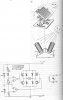
some people requested to post this circuit for the solar tracking system
the circuit is simple. the circuit is a window comparator wich controls the motor until the same light falls on the 2 LDR's
What happens in the morning, when the system has been left pointing West and the sun comes up in the east? It does not appear that either LDR will have light on it.
BTW, nice drawing!
That is an interesting way to do it. I've always seen the control system use dithering. It moves the panel slightly and then measures the power output. If it increased then it moves a little more. If not, it goes the opposite direction.
Yes, that would be the hardest part, to make it track reliably year in, year out, in all kinds of weather, high winds, snow, ice...
Perhaps a worm drive might be a good idea, the big reduction ratio lets you use a small motor and it is not free wheeling.
Angle the panel to your latitude in degrees plus about 10 degrees, to make up for the lower winter sun orbit.
So it just needs to track east to west. You can put in some logic that always returns the panel to fully east after a prolonged no output period (night time). The sun isn't going to rise anywhere else :wink:
The university that I went to had a few panels on the roof of the electrical engineering building (Central Texas). It is a pain to add an active positioning system, so they just adjust them 2x per year to match approximate position of the sun.
I did some brainstorming on the circuit, to see what kind of challenges might be faced. Here are some challenges that I forsee with the system, aside from the mechanics (PS.: The worm gear idea is great!):
1. Figuring the proper diameter and length of the tubes which house the LDR's. Too little diameter, or too much length, and the circuit may spend it's time adjusting to a light amount that cannot be reached by the resolution of the LDR's.
2.Figuring the angle(Pitch) of the support block which is used to support the tubes. Again, too much pitch may produce a resolution point that is too fine for the circuit to "zero" in on.
3. What is the "A" point marked on the left side of the schematic?
4. Figuring the resolution, or output ohm range for the LDR's. LDR's are sold in different models, which output different ranges of ohms for a given light amount. Choosing which one is right is a challenge. I think I may set the circuit up on a breadboard, and use POTS in place of the LDR's to see what kind of ohms output best suits the circuit.
5. Figuring which type of motor is necessary for the axis rotation. Would a stepper motor be well suited here? Too many RPMS with the improper gearing could result in a system that is not capable of finding the best fixed point, and thus not be able to reach the resolution that the LDR's provide (Overcompensation).
6. Figuring the logic to account for the opposing axis operating simultaneously. For instance, axis A may be in the midst of finding the best light point, while axis B is in the midst of finding the best light point. Thus, will the simultaneous operations send the logic of the device to a point where no real zero point is found, and the system sends itself into a perpetual adjusting cycle? I think there needs to be some sort of switch which allows only one of the axis to find the best zero point. Once this is found, or the switch times out, the other axis is allowed to find the best point. So on and so forth until each axis is satisfied.
I did some brainstorming on the circuit, to see what kind of challenges might be faced. Here are some challenges that I forsee with the system, aside from the mechanics (PS.: The worm gear idea is great!):
1. Figuring the proper diameter and length of the tubes which house the LDR's. Too little diameter, or too much length, and the circuit may spend it's time adjusting to a light amount that cannot be reached by the resolution of the LDR's.
I do not think it is that critical, just enough to create a different output from each unless their combined centreline points towards the sun.
2.Figuring the angle(Pitch) of the support block which is used to support the tubes. Again, too much pitch may produce a resolution point that is too fine for the circuit to "zero" in on.
Again, I doubt its too critical, perhaps 30 degrees to start with? What's more importantis that there is nothing reflective nearby to upset the system;-)
3. What is the "A" point marked on the left side of the schematic?
Just some reference for circuit measurement I guess. It should be exactly half the supply voltage for 'on track' condition.
4. Figuring the resolution, or output ohm range for the LDR's. LDR's are sold in different models, which output different ranges of ohms for a given light amount. Choosing which one is right is a challenge. I think I may set the circuit up on a breadboard, and use POTS in place of the LDR's to see what kind of ohms output best suits the circuit.
Idare say that it is not at all critical what range they are, as long as they are reasonably sensitive. The circuit is like a comparator, comparing a fixed input to the op amps to a variable one and wether the variable one is more pos or neg than the fixed input.
5. Figuring which type of motor is necessary for the axis rotation. Would a stepper motor be well suited here? Too many RPMS with the improper gearing could result in a system that is not capable of finding the best fixed point, and thus not be able to reach the resolution that the LDR's provide (Overcompensation).
I think a stepper motor is way overkill, it needs a dedicated drive board, not the 'H' bridge drive shown. Try an old windscreen wiper motor, they usually have a worm drive ( at least some old ones did). It will also run both ways if you disable the parking switch inside it.
6. Figuring the logic to account for the opposing axis operating simultaneously. For instance, axis A may be in the midst of finding the best light point, while axis B is in the midst of finding the best light point. Thus, will the simultaneous operations send the logic of the device to a point where no real zero point is found, and the system sends itself into a perpetual adjusting cycle? I think there needs to be some sort of switch which allows only one of the axis to find the best zero point. Once this is found, or the switch times out, the other axis is allowed to find the best point. So on and so forth until each axis is satisfied.
I frankly would not bother to try this with two axis resolution. The mechanical effort is very unlikely paid back in an sufficient increase of output unless you plan to do this on a very large solar panel.
According to NREL website data most location will achieve a 20% boost in single axis tracking and 40->50% with dual axis tracking.
My pet project requires dual access tracking, its a solar concentrator for hot water. Check out the fun at www.pluggedin.ca/heater.html (if you're bored).
Old satellite dish actuators make great tracking motors.
Does the whole control and steering system consume more power then it gains from increased solar cell output? If so what is the point, just keep it fixed and manual adjust the declanation a couple of times a year. I guess it depends on the size of the solar array being manipulated.
Does the whole control and steering system consume more power then it gains from increased solar cell output? If so what is the point, just keep it fixed and manual adjust the declanation a couple of times a year. I guess it depends on the size of the solar array being manipulated.
I recently built this circuit, and it works nicely. The only question I had for my self at the time was how to make it go back east and the answer I found was a simple curved mirror I found in the junk pile. I just place it by the east sensor in a manor that will start it rotating east, and by the time the reflection runs out the tracker finds the sun.
Solar power is available all over our planet. However there are regions where the sun shines sparingly, e.g. London, which has fog most of the year (I suppose).
To get the most available sun power to the solar panels I guess two criteria must be considered, which are azimuth and elevation.
The appearant path of the sun changes daily between spring time and winter and also the azimuth will change considerably during the four seasons.
Using limit switches (to determine sunrise and sunset position of the sun) will only be valid for one day!
Logically there won't be any limit switch be reached in other times than high summer or winter, depending on the settings of the limit switches.
There is another approach my friend and me are working at. The sun's appearant movements depends on the day, hour and minute including precession and nutation of our globe.
There will be no optical sensors involved to determine the position of the sun. The solar panels follow the inputs of a microcontroller moving the solar panels accurately to the sun's appearant path, no matter if the sky is overast or clear (not of any interest).
There is no "look up table" to be found in the software. All the software does is using formulas to convert the sun's position into precise panel movement accurate to 1/10 degree.
That way you'll obtain the maximum of sunpower for the panel.
The procedure is planned to be as simple as possible to put the panel "on duty" at any location on the globe:
Put in your geographical coordinates in degrees, minutes and seconds of arc, e.g. 16:00:05N, 110:05:15E, plus the local variation from true North.
Upon starting "homing" the system will "find" True North and then synchronize with the sun's path by moving the panel exactly to the calculated position of the sun and follow the sun until sunset.
During night time the panel will return East, not to the same angle as before, but to the angle valid for the new day.
This site uses cookies to help personalise content, tailor your experience and to keep you logged in if you register.
By continuing to use this site, you are consenting to our use of cookies.