Good point Klaus.
I did some brainstorming on the circuit, to see what kind of challenges might be faced. Here are some challenges that I forsee with the system, aside from the mechanics (PS.: The worm gear idea is great!):
1. Figuring the proper diameter and length of the tubes which house the LDR's. Too little diameter, or too much length, and the circuit may spend it's time adjusting to a light amount that cannot be reached by the resolution of the LDR's.
I do not think it is that critical, just enough to create a different output from each unless their combined centreline points towards the sun.
2.Figuring the angle(Pitch) of the support block which is used to support the tubes. Again, too much pitch may produce a resolution point that is too fine for the circuit to "zero" in on.
Again, I doubt its too critical, perhaps 30 degrees to start with? What's more importantis that there is nothing reflective nearby to upset the system;-)
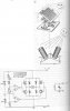
3. What is the "A" point marked on the left side of the schematic?
Just some reference for circuit measurement I guess. It should be exactly half the supply voltage for 'on track' condition.
4. Figuring the resolution, or output ohm range for the LDR's. LDR's are sold in different models, which output different ranges of ohms for a given light amount. Choosing which one is right is a challenge. I think I may set the circuit up on a breadboard, and use POTS in place of the LDR's to see what kind of ohms output best suits the circuit.
Idare say that it is not at all critical what range they are, as long as they are reasonably sensitive. The circuit is like a comparator, comparing a fixed input to the op amps to a variable one and wether the variable one is more pos or neg than the fixed input.
5. Figuring which type of motor is necessary for the axis rotation. Would a stepper motor be well suited here? Too many RPMS with the improper gearing could result in a system that is not capable of finding the best fixed point, and thus not be able to reach the resolution that the LDR's provide (Overcompensation).
I think a stepper motor is way overkill, it needs a dedicated drive board, not the 'H' bridge drive shown. Try an old windscreen wiper motor, they usually have a worm drive ( at least some old ones did). It will also run both ways if you disable the parking switch inside it.
6. Figuring the logic to account for the opposing axis operating simultaneously. For instance, axis A may be in the midst of finding the best light point, while axis B is in the midst of finding the best light point. Thus, will the simultaneous operations send the logic of the device to a point where no real zero point is found, and the system sends itself into a perpetual adjusting cycle? I think there needs to be some sort of switch which allows only one of the axis to find the best zero point. Once this is found, or the switch times out, the other axis is allowed to find the best point. So on and so forth until each axis is satisfied.
I frankly would not bother to try this with two axis resolution. The mechanical effort is very unlikely paid back in an sufficient increase of output unless you plan to do this on a very large solar panel.
Any thoughts?
Have fun.
Klaus
3.