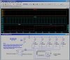
I am a building a solar cell test station that will automatically generate an IV curve of a single solar Cell. I plan on using a circuit to choose among 5 resistors to generate an IV plot. I am only showing one resistor for simplicity. I will also record Isc and Voc. I need help choosing a transistor that will not significantly affect the measurement. If not possible than I will use the transistors to power a mechanical relay. This is a low budget project so ultimate accuracy is not essential.The data acquisition device is a 12 bit minidaq (MiniDaq A/D and I/O board for the IBM PC)
Continue to Site