Continue to Site

Welcome to our site!

Electro Tech is an online community (with over 170,000 members) who enjoy talking about and building electronic circuits, projects and gadgets. To participate you need to register. Registration is free. Click here to register now.

  • Welcome to our site! Electro Tech is an online community (with over 170,000 members) who enjoy talking about and building electronic circuits, projects and gadgets. To participate you need to register. Registration is free. Click here to register now.

SMPS Power Supply Failed Due to Poking a Screwdriver inside (Rush current to Earth left a weld mark on screwdriver earth terminal)

Status
Not open for further replies.
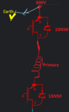
Hello everyone. I have a 500W power supply and my son says he poked the power supply's fan terminal with a screwdriver and the breaker popped while the power supply failed.

Now I am really confused about one thing: When I traced the voltages from the diode bridge ford ( whose 1 diode also failed, replaced and then failed again with another breaker pop which was expected because one kf13n50 MOSFET and 5R06X diode were also initially failed), the positive 300V (220*sqrt(2)) terminal goes to the heatsink plate where the MOSFETs lie on the front of the board. It seems certain that this is deliberate (look at the pads on backside --first image) Who would design in such a way? Why is there an exposed bare 300V aluminum plate- invitation for disaster-? A real WTF moment for me. Next RT11 carries this voltage to the big chunky-boi Capacitor (400V 270uF) which is also okay. RT11 is a PTC thermistor to double the foolproofness. RT11 is normally short and when I heated it up its resistance increased to a few ohms.

PS: All desoldered till the short on the Live-Neutral is removed. I note here that one of the MOSFETs failed during the incident (one of kf13n50's) - its drain and source was shorted- gate to source had 30ohms. The other 2 kf13n50s are okay. I also note here that the 5R06X rectifier diode also failed as it remained short in both directions.
- By tracing I mean tracing it with a multimeter not just visually.
-The kf13n50's (13n50) are "no top terminal" packaged so maybe the reason that plate had to be at 300V would have been the drain contact of the transistor had to be there at 300V? So they had to accommodate for that? back: front:
BACKSIDE: (where most of the circuit is)
1668548985357.png


FRONTSIDE (component names)
1668550034677.png

Since this is well isolated I strongly believe that the failed components are on the floating voltages side not on the other sides of the transformers (e.g. 12V 5V or 3.3V output sides etc.). ( The transformers also looked okay while I am not sure because I read short since this supply is 80+ and needs to be highly efficient so inductor windings on the transformers are thick and very low resistance)


Thank you so much Tony Stewart Nigel Goodwin

References:
Diodes:
1N5408: https://www.mouser.com/datasheet/2/149/1N5408-888344.pdf
uf5408 (last column) : https://www.vishay.com/docs/88756/uf5400.pdf
: 5R06x : https://www.st.com/resource/en/datasheet/stth5r06.pdf

Transistor:
KF13N50: https://www.docdroid.net/e8APRLd/kf13n50-pdf
 
Last edited:
Your 'mistake' was assuming the heatsink wasn't going to be live - it's quite common, particularly in units like this where the entire PSU is in a protective metal casing, which you aren't supposed to open.

Quite possibly your son shorted that heatsink to the metal casing, which has caused the destruction.
 
It is possible the board was designed for regular or generic KF13N50P devices, and supply issues made them use the KF13N50F, which is insulated. Electrically they are the same.
Either way, they both would work. However, if the original design used the "P" version, the drain (center pin) would be electrically connected to the heatsink, hence using it for a 300V rail would make sense actually, and avoid the use of insulating spacers.
It is common in some SMPS to have the heatsink at the HV potential, feeding the switching MOSFETs via the TO220 bare tab.
These guys used the F versions everywhere and still the heatsink is made sure to connect to drain 300V. Now that you say this, I really want to cut/etch that path (Path marked with double arrows and WTF? marker) with a box cutter and make sure that plate is touching nowhere and floating.

Except.... would I be doing a grave mistake here? I think I maybe impeding a safety hazard but, is there more to this? A floating plate hovering over there? Do you think there is more to this ?
 
Your 'mistake' was assuming the heatsink wasn't going to be live - it's quite common, particularly in units like this where the entire PSU is in a protective metal casing, which you aren't supposed to open.

Quite possibly your son shorted that heatsink to the metal casing, which has caused the destruction.
Thank you and sagor1
I only have one more question.

I am also short on components. Can I use a cylindrical diode instead of the rectifier diode 5R06X, whose only qualification seems to be fast reverse recovery time and mountability to the heatsink.

I found 3A cylindrical diodes to replace it and repair the diode bridge. I have a bunch of UF5408G's and 208R diodes from an old project. Can I use one of those and make a custom fit on the heat sink with some thermal paste?

Also I am short on original 1N5408's. It looks like I have to mix diodes in that diode bridge since I only have 2 working 1N5408 diodes left. I am planning 2 UF5408s + 2 1N5408 s to form a diode bridge and 1 UF5408 to replace 5R06X. I note here is that UF5408 is more expensive but it has noticeable 40% higher forward voltage at 3A quoted at 1.7V compared to 1N5408's 1.2V ( But UF5408 gives this value as maximum instantaneous forward voltage, maybe typical value is not that bad, since I also measure the same 0.47V diode voltage on both 1N5408 and UF5408 at low current with the multimeter's diode mode)

1N5408: https://www.mouser.com/datasheet/2/149/1N5408-888344.pdf
uf5408 (last column) : https://www.vishay.com/docs/88756/uf5400.pdf
: 5R06x : https://www.st.com/resource/en/datasheet/stth5r06.pdf

Some people say just connect some common diodes in parallel to get a strong diode(4 paralllel 1N4007s to get 4A) but they can have defects and mismatches in ON voltage? Theoretically, this parallel combination strong diode will be 4A and also a perfect 0.7V, lol!

KF13N50: https://www.docdroid.net/e8APRLd/kf13n50-pdf
As for the transistor, hopefully, without getting scammed, I think I can get my hands on a >10A >500V Rdson<0.5Ohm MOSFET
 
Last edited:
These guys used the F versions everywhere and still the heatsink is made sure to connect to drain 300V. Now that you say this, I really want to cut/etch that path (Path marked with double arrows and WTF? marker) with a box cutter and make sure that plate is touching nowhere and floating.

Except.... would I be doing a grave mistake here? I think I maybe impeding a safety hazard but, is there more to this? A floating plate hovering over there? Do you think there is more to this ?
Yes you would be - LEAVE IT ALONE - it's how it's designed to be, it's not a safety hazard, and it's doing no harm.
 
sagor1 The thing is I can't find a good replacement for the fast diode (5R06x) on this market. Do you have a recommendation? I don't really believe we need 25ns recovery time for a switching power supply!! This application is really slow. A few 100 KHz.... Do you recommend any TO220 packaged Fast diodes? Nigel Goodwin

I wonder if I can turn this from an 80+white to an 80+ Gold by just changing this main switch. Because as I understand it the switch 13N50 (from KEC) is very old (from 2008) and they went cheap on that it has 0.44 Ohm on resistance and this is what limits us. I think these companies are deliberately cheaping out on the cheapest components just to create binning of products to get different stupidly arranged selling points. 80+ gold and 80+ white versions have the same board, same driver and with just inferior switch component on the white version, I think!

There are new versions of it like KPS15N60F from 2015 https://www.docdroid.net/IRZPHxZ/15n60f-pdf with better ratings in all (except maybe a tad bit slower)

I found 15N60F PLS TO 220 version from UTC vendor for under 1$.

There is also 20N60 but it is slower with higher gate capacitance and response times, https://datasheetspdf.com/pdf-file/931299/UTC/20N60/1 but this is probably not critical as this is SMPS with at most a 100KHz switch frequency....


The vendors of those new ones are different (Unisonic Tech. Co.) Why the specs differ so much from vendor to vendor.

20n60
https://datasheetspdf.com/pdf-file/931299/UTC/20N60/1
1668781864174.png

1668781873826.png


There is also no name 6A 1000V diodes I found for 10 pennies each. I think they are from the indian company MIC.
Did you use them before and have any idea if they will be reliable as the other vendors ?
https://www.circuits-diy.com/6a10-1000v-6a-power-diode-datasheet/
How are they rated 6A and so cheap ? And also compared to 1N5408's have much better forward voltage drop of 0.95V ??? Nigel Goodwin

On a side note I still am confused about how the failure happened. Here is a simplified diagram of the transistors and the primary: even if I touch the 300V plate the current should not have damaged the transistor, (rectifier diode 5R06X which is on the path is okay to be damaged, I understand that). From the looks of it (Drain and source shows shorted, ,the intrinsic body diode of the mosfet might have broken down?
1668783194914.png
 

Attachments

  • 1668783071776.png
    1668783071776.png
    25.7 KB · Views: 153
Last edited:
sagor1 The thing is I can't find a good replacement for the fast diode (5R06x) on this market. Do you have a recommendation? I don't really believe we need 25ns recovery time for a switching power supply!! This application is really slow. A few 100 KHz.... Do you recommend any TO220 packaged Fast diodes? Nigel Goodwin

I wonder if I can turn this from an 80+white to an 80+ Gold by just changing this main switch. Because as I understand it the switch 13N50 (from KEC) is very old (from 2008) and they went cheap on that it has 0.44 Ohm on resistance and this is what limits us. I think these companies are deliberately cheaping out on the cheapest components just to create binning of products to get different stupidly arranged selling points. 80+ gold and 80+ white versions have the same board, same driver and with just inferior switch component on the white version, I think!

There are new versions of it like KPS15N60F from 2015 https://www.docdroid.net/IRZPHxZ/15n60f-pdf with better ratings in all (except maybe a tad bit slower)

I found 15N60F PLS TO 220 version from UTC vendor for under 1$.

There is also 20N60 but it is slower with higher gate capacitance and response times, https://datasheetspdf.com/pdf-file/931299/UTC/20N60/1 but this is probably not critical as this is SMPS with at most a 100KHz switch frequency....


The vendors of those new ones are different (Unisonic Tech. Co.) Why the specs differ so much from vendor to vendor.

20n60
https://datasheetspdf.com/pdf-file/931299/UTC/20N60/1 View attachment 139338
View attachment 139339

There is also no name 6A 1000V diodes I found for 10 pennies each. I think they are from the indian company MIC.
Did you use them before and have any idea if they will be reliable as the other vendors ?
https://www.circuits-diy.com/6a10-1000v-6a-power-diode-datasheet/
How are they rated 6A and so cheap ? And also compared to 1N5408's have much better forward voltage drop of 0.95V ??? Nigel Goodwin

Speed is important, because the slower the speed the hotter it runs - and the quicker it fails (which could be seconds). Using cheap no name (or fake) devices is a recipe for disaster as well - use properly specified high quality components. Repairing SMPSU's is tricky enough anyway, and I've repaired thousands of them - not many in PC's though, as they are cheap enough to replace the whole PSU, and particularly badly designed to be difficult to work on.

On a side note I still am confused about how the failure happened. Here is a simplified diagram of the transistors and the primary: even if I touch the 300V plate the current should not have damaged the transistor, (rectifier diode 5R06X which is on the path is okay to be damaged, I understand that). From the looks of it (Drain and source shows shorted, ,the intrinsic body diode of the mosfet might have broken down?

SMPSU's are like a chain of dominoes, it just needs something to start it 'toppling', I see nothing strange in the chopper transistors having blown - if anything 'nasty' happens in the PSU then they will almost certainly blow. The FET itself will simply be short drain to source, the incidental (accidental?) diode doesn't really do anything.
 
Speed is important, because the slower the speed the hotter it runs - and the quicker it fails (which could be seconds). Using cheap no name (or fake) devices is a recipe for disaster as well - use properly specified high quality components. Repairing SMPSU's is tricky enough anyway, and I've repaired thousands of them - not many in PC's though, as they are cheap enough to replace the whole PSU, and particularly badly designed to be difficult to work on.


SMPSU's are like a chain of dominoes, it just needs something to start it 'toppling', I see nothing strange in the chopper transistors having blown - if anything 'nasty' happens in the PSU then they will almost certainly blow. The FET itself will simply be short drain to source, the incidental (accidental?) diode doesn't really do anything.
I fail to see why any of this should be surprising to someone who knows anything about them. The same principles apply to diverse systems
 
There are replacement diodes similar to the 5R06X, like the VS-8ETH06-M3. It is available on Newark.com for $0.99 each.
It is rated 600V, 8A and recovery is as good as the original diode or better. However, this is an un-insulated one, not sure if the original as encapsulated in plastic or had a bare tab.
If you need an insulated one, the RFUH5TF6SC9 or RFUH5TF6SC9 types may do (both in stock), as well as the STTH8R06FP.
 
sagor1 Nigel Goodwin Papabravo

I managed to repair this one. I replaced the fast diode with MUR1560 https://www.onsemi.com/pdf/datasheet/mur1520-d.pdf it has trr of 60ns, the kf13f40 with a 15n60.
The transistors are of this brand with an italic "F" sign: FQP15N60C and FQP20N60 -- these things are on AliBaba in pricing less than 2 Yuan a piece 10-20 pennies a piece ! https://datasheetspdf.com/pdf-file/1342790/OuCan/FQPF15N60/1 One brand name comes with OuCan I don't know what this means.
1670888499442.png

1670343892161.png

the diode bridge diode MIC 6A10: (anyone know these components?)
1670344317775.png

I checked almost everything with a thermal camera, and saw that there is literally almost zero temperature increase on the TO220 heatsink mounted components, but again, this measurement should be repeated during 100% power draw of 500W.
The only noticeable increase in temperature compared to ambient is now on the bridge diode (52 degree) which I had renewed with MIC 6A10 6A 1000V diodes(but the fan was not blowing on them). I suspect a considerable amount of the idle power draw is dissipated here on the bridge and the FAN(12V*200mA=4.8W) +5.2W. 5.2W on a surface area of these diodes looks okayish ?
the diode bridge diode MIC 6A10:
1670342732015.jpeg

1670343252884.png
the second hotspot (on the left) might be an infrared reflection of the first? -- Actually no, that is some component on the secondary side. I could not yet identify because it is blocked by the second heatsink.


It is pulling 50mA on idle (~11W idle power) when I jumpstart it with the cable method. It can give 20W at 70mA current draw with a quick test. I did these tests with a stone 8.2Ohm power resistor in series ( to current limit the setup in case of further failure) ( I also connected an Ampermeter in series to the 220V line to monitor current, also another multimeter to monitor the 300+V capacitor voltage and the AC line voltage at the device's L-N terminals).


Thank you for the comments. Though I still cannot comprehend the mechanism of failure of that single KF13N50 MOSFET (why its pair is alive if that failed?)
 
Last edited:
Status
Not open for further replies.

Latest threads

New Articles From Microcontroller Tips

Back
Top