Electro Tech is an online community (with over 170,000 members) who enjoy talking about and building electronic circuits, projects and gadgets. To participate you need to register. Registration is free. Click here to register now.
Welcome to our site! Electro Tech is an online community (with over 170,000 members) who enjoy talking about and building electronic circuits, projects and gadgets. To participate you need to register. Registration is free. Click here to register now.
Hi,
I would like to generate a signal where it can oscillate between positive and negative using a positive power source. Is it possible to do it this in a very compact manner? I am talking about miniature object and wearable.
These are very precise and good questions which I appreciate. I will try to answer them:
How much current are you looking to supply?
Since we're talking about wearable and small devices, I would say as minimum as possible.
How fast do you want it to oscillate?
I would it to be fast and variable
How accurate does the voltage need to be?
Not sure about this one.
Is the positive supply a battery?
Yes, it is mentioned on the title that I would like to power this by a Coin Cell 3.0 if possible. If not, it can be a lypo as well.
Does it need to be a negative supply or can the output from the battery be reversed to supply the output?
I would like the output from the battery be inverted to negative VDD
Are you wanting a square-wave output or something else?
I need anything to work with so I can experiment
What will the output drive?
The output will drive something like a lever using magnetic field, something similar to the HDD reader arm.
It's a lot but I was hoping to start small that works and build on it.
If you are wanting to reverse the signal to the HDD reader arm, the easier way is to use an H-bridge. https://en.wikipedia.org/wiki/H-bridge
It does rely on the load not being connected to ground, but it is really common, and it the usual way that dc motors are reversed, whether using switches, relays or semiconductors.
It's a lot more difficult if one side of the load has to be permanently connected to the -ve of the battery. It is possible to make a -ve supply from a +ve one but it's a lot of extra work so I suggest you avoid it if possible.
You need to find out how much current the load takes. You might be best to have a trial circuit run from a power supply, to allow you to measure the current. There's no point in making something small if it doesn't do what you want. Once you get a circuit that does what you want, you can measure the current and make the circuit smaller, and have an idea how big the batteries will need to be.
I suspect that the current needed to run an HDD reader arm could be more than a coin cell will provide.
When you say that the oscillation needs to be "fast", that really doesn't help, as "fast" is so subjective. A fast charger on a battery is complete in 15 minutes. Fast internet delivers 1 bit of data about every nanosecond. The fact that you are trying to move something like an HDD reader arm gives much more of a clue. Please tell us about how many times per second (or minute, hour, day or whatever) you want the signal to reverse.
Prototyping this will be the best approach but did not know what is the best way on the switching side. I thought about an H-bridge but it's bulky and potentially will require more power. Sorry about this request being vague, it is because I am brainstorming and I would like to resolve the switching between positive and negative, once I resolve this on paper, I can start building a prototype.
For the oscillation, I am thinking capacitive sensing using PCB traces. The mVs generated can be fed through an Op Amp, let's say 1Mz which will oscillate between VDD and Gnd.
For the switching, I am thinking a dual Mosfets fast enough to turn the arm in either way base on when the signal is at 0 or at the VDD.
I think if the above is achievable we can forget about Inverting the output to negative is too much work.
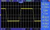
Below is a sample signal I am generating using a capacitive soil moisture sensor soaked in water.
This site uses cookies to help personalise content, tailor your experience and to keep you logged in if you register.
By continuing to use this site, you are consenting to our use of cookies.