Electro Tech is an online community (with over 170,000 members) who enjoy talking about and building electronic circuits, projects and gadgets. To participate you need to register. Registration is free. Click here to register now.
Welcome to our site! Electro Tech is an online community (with over 170,000 members) who enjoy talking about and building electronic circuits, projects and gadgets. To participate you need to register. Registration is free. Click here to register now.
I'll add also a switch to the end RLY, in case the circuit fails or any part of it has been destroyed. That way I can at least drive my mobile scooter home for repair.
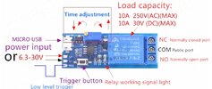
I suppose it will reset after it has been turned off. Have a look at the AliExpress timer modules to learn more about these timer's operation... and please let me know, for I still have not yet built this simple circuit for my mobile scooter, which arrives soon from China. - I'm a young 81 y.o.
Be careful with current loads on the wires and switches & use good quality (automotive grade) wire for abrasion and temperature. You don't want a fire starting under your seat when the last thing on your mind while driving is your warming butt. Also, solder joints on vehicles is typically avoided because they don't handle vibration well (especially with stranded wires) - use crimp connectors.
Having worked at Delphi/Packard Electric for ~30 years, where they make vehicle wire harnesses, I would agree with Zip,zap. Very few of the terminals were soldered and those that were, were soldered using a solder dip on the bare wire, then a crimp and then sonic heated to set the solder. The sonic and dip was to keep the solder from flowing up into the wire strands, that happens when you apply a soldering iron and solder like usual.
- Edit from 50 years to 30 years. -
You get huge shear forces on individual strands when wires are flexed at the solder joint. They break one at a time. Crimping tends to allow some relieve of individual strands within the bundle. A solder joint is even worse when, as Shortbus said, solder is allowed to wick up the insulation. Cord restraints are critical if you are using soldered joints (wire to board).
So they do solder at Delphi.
The vibration on a vehicle with a properly secured harness will make the vehicle fall apart before dislodging a soldered terminal joint.
One in a million starter/battery terminals with a lot of mass prone to rupture may break. Until a genius mechanic treats wiring as pulling weeds, which I have seen, several times.
The Delphi plants I worked in over the years were amazing to me.
They made their own tape, some with adhesive and some without.
They made their own wire starting with coils of copper round stock ~5/16" in diameter and drawn down to the correct diameter, then bunched and covered with insulation.
They made most of their own terminals even the gold plated ones.
They made thier own spark plug wire starting with Kevlar thread and soaked in graphite then covered with 2 different types of rubber, with a braid in between the rubber types.
They made almost all of the plastic connectors that are used in GM cars.
They molded the rubber spark plug boots and cut and assembled the plug wires.
The lead molded starter/battery cable terminals actual had a brass terminal inside the lead.
Thanks to you all for your good advice. I played for over 50 years with electronics at a hobby level, survived lots of shocks... and even accomplished some amazing projects. Such as... turned an old 120-button accordion bass into MIDI via some 250 diodes, building two JANKO keyboards, etc.
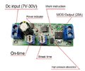
High voltage/ ampere wiring requires correct cable thickness and mechanical joints.
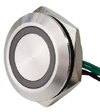
Besides, the pushbutton under the seat is 30mm in diameter very flat and my body weight will securely keep it in a push-down position. If not, I can swap it for a PB, which has a 3cm switching path, such as a pneumatic house floor PB. I still got a few of these. They are now hard to find and nearly $100 (!!)
Maybe there's another way of triggering my presents, such as a light beam?
Very kind of you Lightium. Well then, here are some questions/problems: That PB matter under the seat worries me, that it might jump if the road gets rough. With cars, it can be a driver-door PB but with my mobility scooter, it has to be some kind of reliable sensor that senses my presents in the driver's seat. Maybe an "infrared lightium" will do a better job?
I just bought this (below shown) $A15 infrared barrier on AliExpress. I think this will be much better than an under-seat PB. The scooter battery is 60VDC at 20A. I also bought a converter 60VDC to 12VDC and a 60VDC lead-acid battery rejuvenator/desulfator. That mobility scooter is still in transit from China.
Although it would add complication, I suggest a short timer, maybe a couple of seconds, so that there is no action if the seat switch is released for that time. That would stop there being any effect over bumps, but would not make any real difference if you get out of the car.
This site uses cookies to help personalise content, tailor your experience and to keep you logged in if you register.
By continuing to use this site, you are consenting to our use of cookies.

")