Continue to Site

Welcome to our site!

Electro Tech is an online community (with over 170,000 members) who enjoy talking about and building electronic circuits, projects and gadgets. To participate you need to register. Registration is free. Click here to register now.

  • Welcome to our site! Electro Tech is an online community (with over 170,000 members) who enjoy talking about and building electronic circuits, projects and gadgets. To participate you need to register. Registration is free. Click here to register now.

Remarkably Simple Solar Tracking Circuit

Status
Not open for further replies.

For The Popcorn

Well-Known Member
Most Helpful Member
I saw this amazingly simple solar tracker circuit on LinkedIn, and thought some of you might be interested in it. There's a video following the schematic. A single D2822M audio amp chip, a couple LDRs (Light Dependent Resistor) and a couple resistor are all that's required to drive a geared DC motor to aim a sensor at the sun....and presumably some sort of solar array. The D2822 is an audio amp designed for cassette recorders, but it can be considered as two power op-amps, capable of 700mA output. LCSC.com has D2822Ns in stock.

I'm drawn the schematic here. One change I would make is to replace one of the 10k resistors with a 5k resistor and a 10k pot to adjust out any difference in the LDRs.

D2822 Solar Tracker.jpg


I dont see any inductive transient protection for the DM2822 outputs so
would be concerned that should be added. Or Power supply disconnect
protection.


Regards, Dana.
 
There is no hysteresis and no dead zone, so one motor or the other will be full-on at all times. When the circuit is balanced (pointed directly at the sun), the two outputs will toggle constantly, causing the (dish, solar panel, whatever) to flutter back and forth.

ak
 
Unfortunately there are loads of similar useless 'projects' on YouTube - easily identified as they just solder the components together in mid-air - no attempt at proper construction, or indeed any kind of design.
 
I'd think that as it's an audio amp IC, with fixed linear gain, the output imbalance will be very low when the inputs are equalised..
No dead zone, but proportional motor speed from the error magnitude, as long as the motor load is small enough.
 
Unfortunately there are loads of similar useless 'projects' on YouTube - easily identified as they just solder the components together in mid-air - no attempt at proper construction, or indeed any kind of design.
Is there any good solar tracking circuit that you can recommend? Thanks in advance.
 
Is there any good solar tracking circuit that you can recommend? Thanks in advance.
I've never bothered looking for any - but the basic principle above is reasonably sound - just that it's been stripped down until it's really crap. Personally, if I was doing it I'd use a PIC to do it. so it's easily and instantly configurable.

Are you sure it's worthwhile adding solar tracking?, a correctly aligned fixed system is pretty good - and you waste power moving the dish.
Also the cost of the machinery to move the solar panels could go towards buying more solar panels instead.
 
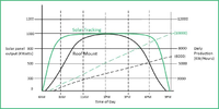
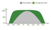
Tracking versus fixed :

1667857077583.png


1667857091463.png


Regards, Dana.
 

Attachments

  • 1667856996578.png
    1667856996578.png
    105.6 KB · Views: 281
  • 1667857022992.png
    1667857022992.png
    53.1 KB · Views: 278
Last edited:
Are you sure it's worthwhile adding solar tracking?, a correctly aligned fixed system is pretty good - and you waste power moving the dish.
Our house does not point in the ideal direction for our solar system and while talking to the installers, their comment was, a tracking system can substantially increase the generated power over a day, especially during winter.
 
Our house does not point in the ideal direction for our solar system and while talking to the installers, their comment was, a tracking system can substantially increase the generated power over a day, especially during winter.
I'd be more impressed with figures - rather than a vague 'substantially' - which is completely meaningless. I'd also like to hear how much power the tracking itself consumes?.

It's rather telling that all the masses of solar farms you see don't use tracking!.
 
I agree with Nigel.

There are lots of factors which affect what would make a tracking system worthwhile, and my cynical view is that the installers make money from installing more stuff, so they would say that, wouldn't they? Actually working out what is the best value for money is really difficult. In some places, there can be partial shading of the panels and some arrangements handle that better than others. A tracking system could make that worse.

Arguably, a well designed tracking system will only use power for very short periods, so its daily energy consumption should be tiny.

If you've got no more roof space to put more panels, then more investment can't go on more panels, which would favour a tracking system over more panels. A solar farm may have fewer space constraints.
 
Just looked at 12 sites, they pretty consistently report single axis
tracking at +20%, dual at 30-40%. Unless they are using engine
from Titanic to move the array hard to imagine all that additional
generation is eaten up by the tracking motor use.

Must be some government and ASEE and IEEE and .....studies on this
that would suffice in a world that needs 10^256 answers to affirm some-
thing is true. Do electron's really flow in a wire ? Is the earth round, sure
looks flat to me when I stand on the crust. I have many doubts.

Regards, Dana.
 
I'd be more impressed with figures - rather than a vague 'substantially' - which is completely meaningless. I'd also like to hear how much power the tracking itself consumes?.

It's rather telling that all the masses of solar farms you see don't use tracking!.
Just google "solar farm tracking", look at images, seems like a lot of hits.


Regards, Dana.
 
I'd be more impressed with figures - rather than a vague 'substantially' - which is completely meaningless. I'd also like to hear how much power the tracking itself consumes?.

It's rather telling that all the masses of solar farms you see don't use tracking!.


challenge accepted, hopefully i will have one built over winter.
but how will i get an accurate power reading of the amps generated?
 
I believe the addition of a pot or resistor in the P2 positiion as shown in this circuit, from DIY Solar Tracker Circuit, would solve some of the objections to this simple circuit. Still drive the motor directly from the amp outputs and eliminate the h-bridge.


1667933762181.png
 
wowzers. I just signed up here. I hope every thread isn't like this. This circuit is just for fun. no one is making it into a solar tracker for their house. It's for a tiny little BEAM Robot type thing. It's OK to have a little fun.
 
wowzers. I just signed up here. I hope every thread isn't like this. This circuit is just for fun. no one is making it into a solar tracker for their house. It's for a tiny little BEAM Robot type thing. It's OK to have a little fun.
If building something basic bound to badly work if at all is fun, then go ahead.
 
Status
Not open for further replies.

Latest threads

New Articles From Microcontroller Tips

Back
Top