When a load causes the collector current to to have a higher current swing then the emitter current also has the same increased current swing.
...
Sorry AG but you are talking complete nonsense!
Given a Vin of 1.6v there is a fixed Vb of 1.6v, which will NOT change as there is no negative feedback from the output of the amp back to the base.
With a fixed Vb of 1.6v you get a Ve of 1.0v due to the open loop properties of the B-E junction dropping approx 0.6v. With Ve of 1.0v and 1k Re you get a fixed Ic of approx 1mA.
This is *fixed* at 1mA as there is no negative feedback from the output of the amp to either the base or to the emitter.
So the amp functions as
an open-loop constant current sink where current sunk into the collector (Ic) is fairly linearly proportional to changes in Vb.
BUT Vb is fixed, and it in turn fixes Ve and Ic, and there is NO negative feedback of the amp output (Vc) to either base or emitter so when the collector is loaded its voltage drops accordingly, and Vb and Ve and Ic all remain fixed and unchanged!
I have no idea where you get "increased load current causes increased emitter current".

MrAl said:
It's not just a function like negative feedback; it is negative feedback.
...
It is negative feedback of Ic, but NOT negative feedback of the AMP. See what I said to AG above. The AMP runs very much as open-loop.
MrAl said:
...
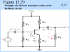
Down near the bottom, there's a figure labeled "Voltage amplifier". To the left of that figure in the text, you'll find: "We observe that the output current is sampled, by the 1k emitter resistor, and the voltage across this resistor is fed back to the input (the emitter is the "inverting input" of the transistor) with the proper phase to give negative feedback. Therefore, we have series-series feedback in this case."
Not right.
The amp's "output current" is not sampled at ALL. That is the problem! The current that is "sampled" is the current sunk into the collector. That is NOT the output current of the amp. Output current of the amp is current drawn into the load, and is entirely separate to Ic and not will not affect Ic (as Ic is a constant current sink).
(Please see circuit C in my post #43 above)
As I said to AG, if you draw current FROM the amp output, the emitter current remains fixed and the amp output voltage Vc drops in response with load. It doesn't get any more open loop than that.
Given a load, there is no negative feedback from Vc to either Ve or Vb in response to the load.
")