Continue to Site

Welcome to our site!

Electro Tech is an online community (with over 170,000 members) who enjoy talking about and building electronic circuits, projects and gadgets. To participate you need to register. Registration is free. Click here to register now.

  • Welcome to our site! Electro Tech is an online community (with over 170,000 members) who enjoy talking about and building electronic circuits, projects and gadgets. To participate you need to register. Registration is free. Click here to register now.

Simple transistor headphone amp

Status
Not open for further replies.

carbonzit

Active Member
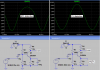
Playing around with this little audio amp, I came up with a nice simple little 3-transistor amplifier that drives a set of headphones very nicely.

**broken link removed**

I like it because 1) it's simple, 2) it only uses 3-legged devices, and 3) it can be built from parts in your junk box.

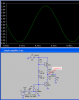
I listened quite a while with this running on a 9 volt supply, and it sounded good to me. It took a while to tweak the input attenuator network (R1 & R2) so that it wouldn't be too loud, the volume control would actually work (instead of acting as an "on-off" switch) and the input would be inaudible with the volume control at its leftmost position.

I actually ran this without any output coupling capacitors with seemingly no ill effects either on my headphones (mid-range Koss) or my ears, so I'm not convinced they're absolutely necessary.

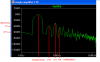
I powered this with Mr. Al's simple 3V--> 9V boost converter, which worked great. (Had to throw about 1000µF of filter capacitor across the power rails to quiet it down.)
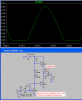
 
Last edited:
I was wondering about that too. The author said they could be replaced by a single resistor between emitters. In that case, does it matter where you take the output? It doesn't affect the symmetry of the output waveform, does it?
 
You don't need any emitter resistors as the two transistors are emitter-followers and there is a point when neither transistor is conducting so no resistors are needed (they are normally added to prevent high currents from flowing).
 
I simulated it. It has a voltage loss of 0.6 times instead of a voltage gain.
It has horrible distortion of about 3% near clipping.
It is biased wrong so it clips the bottom before the top.
It has crossover distortion if the 4.7 ohm resistors are removed.
 

Attachments

  • simple headphones amp.PNG
    simple headphones amp.PNG
    21.6 KB · Views: 686
I simulated it. It has a voltage loss of 0.6 times instead of a voltage gain.
It has horrible distortion of about 3% near clipping.

How do you know this? I don't see any distortion analysis in your simulation. Did you do a FFT analysis?

It is biased wrong so it clips the bottom before the top.

Again, how do you know this? The output waveform looks fine to me. And what level is the amp running at in your simulation? If it's working at the top of its lungs, then no wonder you're seeing these faults.
 
How do you know this? I don't see any distortion analysis in your simulation. Did you do a FFT analysis?
Many people cannot see 10% distortion on a 'scope but with my long experience I can see 0.5% to 1% distortion.
The FFT shows what I said: Lots of horrible distortion.

Again, how do you know this? The output waveform looks fine to me. And what level is the amp running at in your simulation? If it's working at the top of its lungs, then no wonder you're seeing these faults.
It is nowhere near clipping. It is biased wrong so its clipping is not symmetrical.

Normal amplifiers have almost no distortion up to clipping. The inexpensive LM3886 60W amp IC has 0.002% distortion at clipping.
 

Attachments

  • simple headphones amp FFT.PNG
    simple headphones amp FFT.PNG
    13.8 KB · Views: 485
  • simple headphones amp clipping.PNG
    simple headphones amp clipping.PNG
    23.2 KB · Views: 506
  • LM3886 clipping distortion.PNG
    LM3886 clipping distortion.PNG
    29.5 KB · Views: 494
Normal amplifiers have almost no distortion up to clipping. The inexpensive LM3886 60W amp IC has 0.002% distortion at clipping.

So you're comparing my little 3-transistor headphone amplifier to a 60+W LM3886?

Yeah, that's a fair comparison! Sheesh.
 
So you're comparing my little 3-transistor headphone amplifier to a 60+W LM3886?

Yeah, that's a fair comparison! Sheesh.
The headphones amps at Headwize.com use an opamp with 0.00008% distortion and they add a load resistor so it operates in class-A for even LESS distortion. They are audiophools.
The LM3886 60W amp IC costs $7.30 at Digikey today.
A fairer comparison is the 1/4W LM386 IC that costs $.95 today. Its distortion is 0.2% at clipping into 8 ohms and nearly nothing when driving 32 ohm headphones (but it has hissss).
 
The headphones amps at Headwize.com use an opamp with 0.00008% distortion and they add a load resistor so it operates in class-A for even LESS distortion. They are audiophools.


**broken link removed**audiophool

One who spends mass amounts of cash on ridiculous Audio components and accessories. They truly believe they can tell a difference, and come up with elaborate excuses to justify these purchases.
" 'I just bought a set of $5,000 isolated marble cable-elevators to keep my $12,000 oxygen-free silver audio cables from touching the floor and picking up vibrations.'

Ahhh...I'm an audiophile not a phool(fool?), and thanks for this new word :D
 
I simulated it. It has a voltage loss of 0.6 times instead of a voltage gain.
It has horrible distortion of about 3% near clipping.
It is biased wrong so it clips the bottom before the top.
It has crossover distortion if the 4.7 ohm resistors are removed.

Audioguru, that was cool of you to build it in the simulator and run some tests and provide the feedback on it's failings.

I'm curious of what simple easy changes you would make to this 3 transistor amp to improve it?

Bearing in mind that it's easy to say "this amp sux" but people who open this thread based on the thread title may be genuinely interested in a simple cheap headphone amp made from a couple of transistors.

Without adding too much or changing it much what would you "tweak" to improve it?
 
Without adding too much or changing it much what would you "tweak" to improve it?

I'm not the one you asked, but I removed the unneeded emitter resistors, and reduced the upper base resistor, which seems to help the asymmetrical clipping problem a bit:

**broken link removed**
 
Audioguru, that was cool of you to build it in the simulator and run some tests and provide the feedback on it's failings.

I'm curious of what simple easy changes you would make to this 3 transistor amp to improve it?

Bearing in mind that it's easy to say "this amp sux" but people who open this thread based on the thread title may be genuinely interested in a simple cheap headphone amp made from a couple of transistors.

Without adding too much or changing it much what would you "tweak" to improve it?
I made it as good as possible by biasing the input transistor properly and adding bootstrapping with R7 and C2. I connected the negative feedback source to the output of this amp.
Now its output power (voltage swing) can be much more than before but it causes distortion.
I made its gain and output level the same as before so the FFT graph can show much improved distortion.
But its gain is provided by only a single transistor that causes a lot of distortion when gain is added.
Most half-decent simple amps have this input transistor as a driver transistor and have an added transistor at the input (or two transistors to make a differential amplifier) which adds a lot of gain so the negative feedback can be much more to reduce distortion.
 

Attachments

  • simple headphones amp improved.PNG
    simple headphones amp improved.PNG
    37.7 KB · Views: 500
I'm no amp expert, but why not use an emitter resistor to gnd on Q1, to set the gain of Q1 as a common emitter stage, assuming it needs a voltage gain of maybe 3 as a headphone amp from a line input.

Then DC bias Q1 better with 2 resistors 9v-base and base-gnd to give a better output swing. And change to a 32ohm load which is more typical of all the tiny headphones people use now...

And drop the negative feedback. ;)
 
I'm no amp expert, but why not use an emitter resistor to gnd on Q1, to set the gain of Q1 as a common emitter stage, assuming it needs a voltage gain of maybe 3 as a headphone amp from a line input.
Then the all-over negative feedback is less so the distortion is higher. I tried it and that is what happened.

Then DC bias Q1 better with 2 resistors 9v-base and base-gnd to give a better output swing.
A single resistor connected to the output of the two output transistors gives good DC negative feedback to control the biasing.

And change to a 32ohm load which is more typical of all the tiny headphones people use now...
Then the distortion of my latest circuit is about half.

And drop the negative feedback. ;)
Negative feedback from the output reduces distortion and decreases the output impedance.
A half-decent amplifier has an output impedance of 0.04 ohms or less, some are 0.008 ohms. Then the resonances of a speaker are damped and the output swing doesn't change with frequency as the impedance of a speaker changes.
 
Last edited:
Thanks for the info AG. :)

...
re; use 32 ohm load not 8 ohm; Then the distortion of my latest circuit is about half.
...

Well that should be plenty good enough then? How much fidelity is needed? I would imagine this amp would be used for non critical things like test gear, signal tracers, etc, any case where it's not necessary to use a HiFi quality amp chip?
 
Hi Mr RB,
Have you seen how much distortion is caused by a single transistor without any negative feedback and at high levels? The distortion compresses the top of the waveform so much that you cannot see how much voltage gain there is. That is one reason that opamps have so many transistors.
 

Attachments

  • sim transistor distortion1.PNG
    sim transistor distortion1.PNG
    34.2 KB · Views: 476
Status
Not open for further replies.

Latest threads

New Articles From Microcontroller Tips

Back
Top