Continue to Site

Welcome to our site!

Electro Tech is an online community (with over 170,000 members) who enjoy talking about and building electronic circuits, projects and gadgets. To participate you need to register. Registration is free. Click here to register now.

  • Welcome to our site! Electro Tech is an online community (with over 170,000 members) who enjoy talking about and building electronic circuits, projects and gadgets. To participate you need to register. Registration is free. Click here to register now.

Simple Diode question....

Status
Not open for further replies.

AtomSoft

Well-Known Member
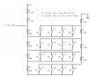
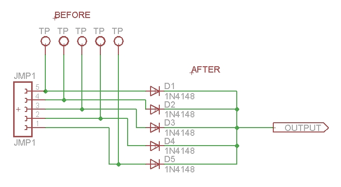
ok would it be possible to use a diode for connecting multiple lines without them actually touching like the below image.

I want to tie some lines together to determine if any 1 line went high. So if 1 line went high then i know to check them all to see which one it was.

To determine if HIGH i check output on the after diode... To determine which one went high i check the TP (test point) on the before diode

would this work?

diodeq-jpg.35889
 

Attachments

  • diodeq.jpg
    diodeq.jpg
    50.7 KB · Views: 682
Last edited:
Hi there,


Just a quick note:
You may want to add a 10k resistor from the output of the diodes to ground
to make sure the output is at a logic 'low' when all the inputs are low.
Other than that i dont see any problem. The output of the diodes will
go high if any one of the inputs goes high, and that seems to be what
you want.
Not sure what you mean by saying that you dont want the diodes 'touching'.
 
heh... The main thing i need to do is make a INTERRUPT type situation. Where i have 5 buttons pulled low...

I want to use 1 interrupt line on a pic... Now using the schem i made above i will connect the diode output to the pic and the other lines to the buttons so when you press any button.... the output (interrupt) line goes high telling me to poll the buttons which then i can check the TP RA0-RA5 for which went high.. This way i save on interrupt lines....

You get it?
 
Last edited:
That will work but you could do it easier with interrupt on change.

Which chip are you using?

Mike.
 
Ok here is what i have in mind tell me your thoughts...

control-jpg.35891


Ok since the 74xx166 has a latch which is active low i will use a NPN transistor to connect it to gnd when a button is pressed. It is pulled high when not in use...

Now when the user presses a button which is pulled low... the line goes high and also sets the latch and the Interrupt line to the pic. Which then the pic will read the latched data using the serial wires con the Jumper (TO PIC)

Does this sound like it will work?
 

Attachments

  • control.jpg
    control.jpg
    105 KB · Views: 618
Last edited:
Use a pic with more pins. After all PIC stands for Peripheral Interface Controller. They were designed to replace TTL chips.

Mike.
 
This was made out of boredom and the issue is the max pins on a pic i plan to deal with is 40 PIN. Now the issue with that is that im sure i will be in need of pins... The issue is if i have 8 buttons i dont want to waste a whole port on it. I rather have some type of expansion....

My question is..... is the above doable? Do you think with your knowledge it will work?
 
It will work but I normally use 9 pins to interface an LCD and a 3x4 keypad.

Mike.
 
What are you making? It looks like a keyboard matrix sorta. You can use a '373 data latch to detect a high. In a KeyBrd matrix the processor pulls all columns (X,Y graph) high that feed to the switches (keys) then reads the rows to see if any are high. If so, then it turns on individual columns and reads the data latch. If not high it turns off that column and turns on the next until it finds the high. Then by the processor knowing which data line on the latch is high it can use a look-up table to determine which key was pressed.

It's all done in the interrupt. So any key pressed will trigger the interrupt.
 
Last edited:
ok the main idea came from a NES controller but i noticed it was a poll system and interrupt would be better in my case...

NES SNES Famicom Controllers!

I want to be able to test either buttons or other devices like this. Meaning all will be treated as a interrupt and still have there own lines on 74xx166 so i can read the data easy

Yeah, KeyBrd matrix is what you want. Wish I had time to draw you one real quick but it's pretty simple. If you turn on all the columns through output ports, then tie the switches which in your case may be diodes, then in the case of the switches, the other side of the switch goes to the columns and into the data latch and back to input ports on the processor. So if any switch is pressed, the latch is transparent so a high will appear at the processor's input ports which with be configured for change state. Actually the latch is not really needed since the input ports can be configured the same way.

So once it sees a high it goes into the ISR which will turn on individual columns until it finds the high and reads the appropriate data input. Then you form a look-up table that says = when column X is on and row Y is on then this is the key or device or whatever it is you are trying to locate.

There is also a Daisy Chain method as well. It's used in PC PICs (8259- Priority interrupt Controller)
 
heh that sounds simple enough but i still prefer this method since there is no need to have a lookup table since the data recieved is 1 byte.

Im sure i could make a simple 4x4 pad...
 
heh that sounds simple enough but i still prefer this method since there is no need to have a lookup table since the data recieved is 1 byte.

Im sure i could make a simple 4x4 pad...

Put it into application then see...lol ;) Not trying to be a wise guy. GL
 
Hi, Atomsoft. I recently thought of a way (theoretically) that allows someone to use a single ADC pin to detect a press of a 4x4 keypad. It uses a handfull of resistors in a divider situation, see attached diagram. When nothing is pressed, there is a pullup resistor only. Pressing a key produces a voltage out of the divider from ~1.9V to 3.55V. If you connect the divider also to a comparator, you can have it detect the drop below 4V. Just connect the comparator's output to an interrupt-on-change pin to have the processor take a reading of the divider's output, figure which key was pressed, and act accordingly. If this interests you, I could even add the comparator to the diagram and put the new version here. My design was just going use a constant poll of the ADC pin in the main routine.
Hope this helped.
kenjj

Later: Ignore the diagram here. Go to the corrected diagram below!
 

Attachments

  • KeyPad Using ADC.JPG
    KeyPad Using ADC.JPG
    52.2 KB · Views: 186
Last edited:
Hi Jason,

You can also Charlieplex switches (with diodes) so 3 pins = 6 switches, 4 pins = 12 switches, etc...
 
Status
Not open for further replies.

Latest threads

New Articles From Microcontroller Tips

Back
Top