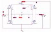
Quit looking at pspice and start looking at spec sheet, as clever duck suggested. Look at the curve for source-drain current vs. Vgs. At 5V, this may not be enough to deliver the 200ma through the 25Ω load.
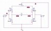
Also, you may have blown the drivers since you had them upside-down.
...assuming you actually built this. Are you just doing simulations?

")