Continue to Site

Welcome to our site!

Electro Tech is an online community (with over 170,000 members) who enjoy talking about and building electronic circuits, projects and gadgets. To participate you need to register. Registration is free. Click here to register now.

  • Welcome to our site! Electro Tech is an online community (with over 170,000 members) who enjoy talking about and building electronic circuits, projects and gadgets. To participate you need to register. Registration is free. Click here to register now.

Simple circuit please

Status
Not open for further replies.

vigilante

New Member
Hi guys, could someone draw me a simple circuit please?
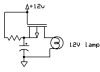
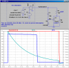
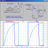
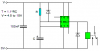
I want it to light a bulb for approx 2-3 seconds when powered, and then the bulb to go off while the circuit remains powered (12volts)
I havn't a clue regarding electronic theory, but can follow instructions well.
Thanks
Dave
 
You want the light to snap off, or can it extinguish slowly? How watts/amps is the bulb?
 
Last edited:
Use a 555 timer and a relay to produce a timer relay.

The bulb goes in series with the normally open relay contacts.
 

Attachments

  • 555 delay off..PNG
    555 delay off..PNG
    1.2 KB · Views: 347
Here is a circuit I just thought of. It uses a P channel mosfet as a high side driver. Initially the capacitor is discharged and the mosfet is fully on, as the capacitor charges the mosfet will turn off.
 

Attachments

  • lamp delay off..png
    lamp delay off..png
    3.4 KB · Views: 156
Snap off...........:)...and it's a tiny pea bulb.

Try this one. Uses my favorite part, the LM431. It does the delay each time power is applied, and resets when power is removed, even for a short time. It is the input bias current of the LM431's opamp that charges the timing capacitor. The capacitor discharges through the diode, the lamp, and the 10K resistor.
 

Attachments

  • D20.png
    D20.png
    37.7 KB · Views: 173
Here is a circuit I just thought of. It uses a P channel mosfet as a high side driver. Initially the capacitor is discharged and the mosfet is fully on, as the capacitor charges the mosfet will turn off.

It works once when the capacitor is discharged. However, when the 12V is disconnected, there is nothing to discharge the capacitor. I had to add the diode and resistor to discharge the timing capacitor for each subsequent cycle.
 

Attachments

  • D21.png
    D21.png
    38.5 KB · Views: 137
Here is a circuit I just thought of. It uses a P channel mosfet as a high side driver. Initially the capacitor is discharged and the mosfet is fully on, as the capacitor charges the mosfet will turn off.

The gate voltage never changes. I'd connect the gate to the juncton of the resisitor and cap, and connect the source to ground.
 
The absolute max cathode current rating for the LM431 is 150ma. Most GOW lamps are ~75mA.

Don't you mean the TL431?

The datasheet for the LM431 says 100mA, the TL431 is rated to 150mA.
 
Don't you mean the TL431?

The datasheet for the LM431 says 100mA, the TL431 is rated to 150mA.

I just went and looked up the National, TI and Fairchild versions. All three are the same as the partial data sheet for the LM431, below:
 

Attachments

  • 431c.png
    431c.png
    47.6 KB · Views: 128
Sorry, yes of course you're right, I was confusing the recommended operating current with the absolute maximum rating.
 
Last edited:
hi there i'm new here...i've got sort of similar problem like op but really dont want to hijack the thread but how do i create a new post pls? or should i just forward my circuit diagram here? pls help TIA
 
hi there i'm new here...i've got sort of similar problem like op but really dont want to hijack the thread but how do i create a new post pls? or should i just forward my circuit diagram here? pls help TIA

Go to the index page for the forum you want to post in. Click on the +Post New Thread button.
 
Status
Not open for further replies.

Latest threads

New Articles From Microcontroller Tips

Back
Top