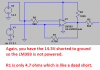
Continue to Site

Welcome to our site!

Electro Tech is an online community (with over 170,000 members) who enjoy talking about and building electronic circuits, projects and gadgets. To participate you need to register. Registration is free. Click here to register now.

  • Welcome to our site! Electro Tech is an online community (with over 170,000 members) who enjoy talking about and building electronic circuits, projects and gadgets. To participate you need to register. Registration is free. Click here to register now.

Simple Bench Power Supply 10A

Status
Not open for further replies.
I do not know what the comparator will drive.
You made many mistakes on your schematic that I fixed except for R5.
 

Attachments

  • comparator.png
    comparator.png
    130.5 KB · Views: 175
Comparitors usually have open collecor or open drain ouputs, so thay can't source current. See the datasheet here: https://www.google.com/url?sa=t&rct...=ZFfSvCgmjZNjfhsK0J5DSw&bvm=bv.78677474,d.cWc

You have to design for 6 mA or the minimum sink current thats guaranteed.

Disabling, basically means you should pick inputs which would result in 0 output in this case. Because of the high input Z, you should have the comparator inputs somewhere. Vcc and ground would be fine, but you would RATHER the output transistor to be off, not on. Usually a resistor is inserted in series with the In+ and In- lines as well. Whatever you have handy or used elsewhere in your circuit, e.g. 10K
 
Your circuit is still completely wrong:
 

Attachments

  • comparator again.png
    comparator again.png
    8.6 KB · Views: 155
Well i am back with this project.
Sorry for long absence but had many work and some more things to do
I now thanks god found the time to continue this project

I decided finally not to use a voltage comparator because of absence of time and want to finish this project.
So as i have described at earlier post i will use the switch for low and hi voltage transformer.

ss.jpg

Below is a little progress i have done with it today !

20150208_223948.jpg
20150209_014013.jpg
20150209_013926.jpg
20150209_015129.jpg


Must mention that i did not drill the holess yet for the potentiometers...

Have it in mind to paint it but haven't decided the color
Any ideas what color to paint it ?
 
The comparator isn't needed for hysteresis because the relay has hysteresis. Alternatively you can get positive feedback using one resistor from the unregulated DC to the base of the relay drive transistor.
 
The comparator isn't needed for hysteresis because the relay has hysteresis. Alternatively you can get positive feedback using one resistor from the unregulated DC to the base of the relay drive transistor.

Magnetic relays do have hysteresis, but make/break delta is very wide, and probably not useful for this application.
 
Have installed the switcing power supply for the 5V usb ports and led's Hi Low indication

usbps.jpg


Have put almost everything together and soldered 220V wires to the transformers,power switch, fuse transformer switcher...

20150213_233454.jpg


And Video from the Hi Low LED indication :)


I hope to finish this soon!
The PS front panel and cover will be painted tomorrow i hope. Will post the results
 
Hi,

Very nice. Where did you get the case?
 
Status
Not open for further replies.

Latest threads

New Articles From Microcontroller Tips

Back
Top